Research Issues
As outlined in the data-recovery plan developed for this investigation, archaeological excavations of the Aramingo Canal were designed to answer a number of research questions related to the construction and abandonment of this former public highway. The research questions included:
- By what means was the Aramingo Canal created within the meandering Gunner’s Run stream channel?
- What materials were used to construct the sidewalls of the canal prism, and in what specific manner were these materials fitted together?
- How deep was the active canal channel in this location?
- Was the bottom of the canal prism lined or prepared in any specific manner and, if so, what methods or materials were used in this aspect of the canal’s construction?
- How does the construction of the Aramingo Canal compare/contrast with other well-documented canals in the surrounding region?
- What were the specific means used in abandoning the canal? Does the wooden structure exposed during initial Phase I/II testing relate to the closing of the canal and, if so, in what capacity?
Research questions were also related to the history of the canal, the nature of its use by adjacent commercial interests and residents, and its impact on the development of the surrounding communities. Historical documentation, detailed in Chapter 2, focused on providing information to answer the following research questions:
- In what ways did the use of the canal change over time?
- In what ways was the canal used by local communities in its later years, when it appears to have been considered a public nuisance?
- What can artifact deposits within the canal prism tell us about this latter period of its history?
- What types of commercial ventures did the canal support?
The next section outlines the land-use history at the location of the data-recovery investigations, and provides the background for subsequent discussions of the structure and materials of the Aramingo Canal. The third section describes the construction of the sewer within the Aramingo Canal, providing the basis for interpreting the features identified in the Phase I/II investigations. Finally, historical documentation and field results are combined to address research questions related to historical use and impact of the canal.
History of the Property
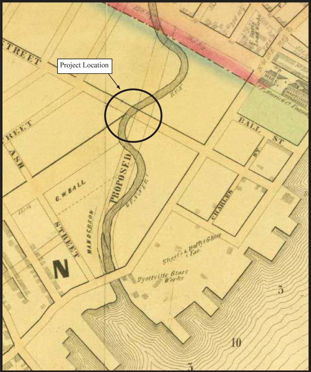
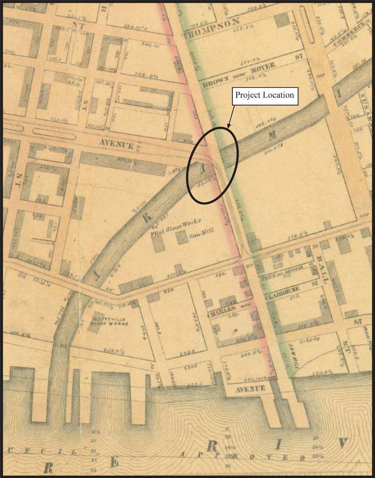
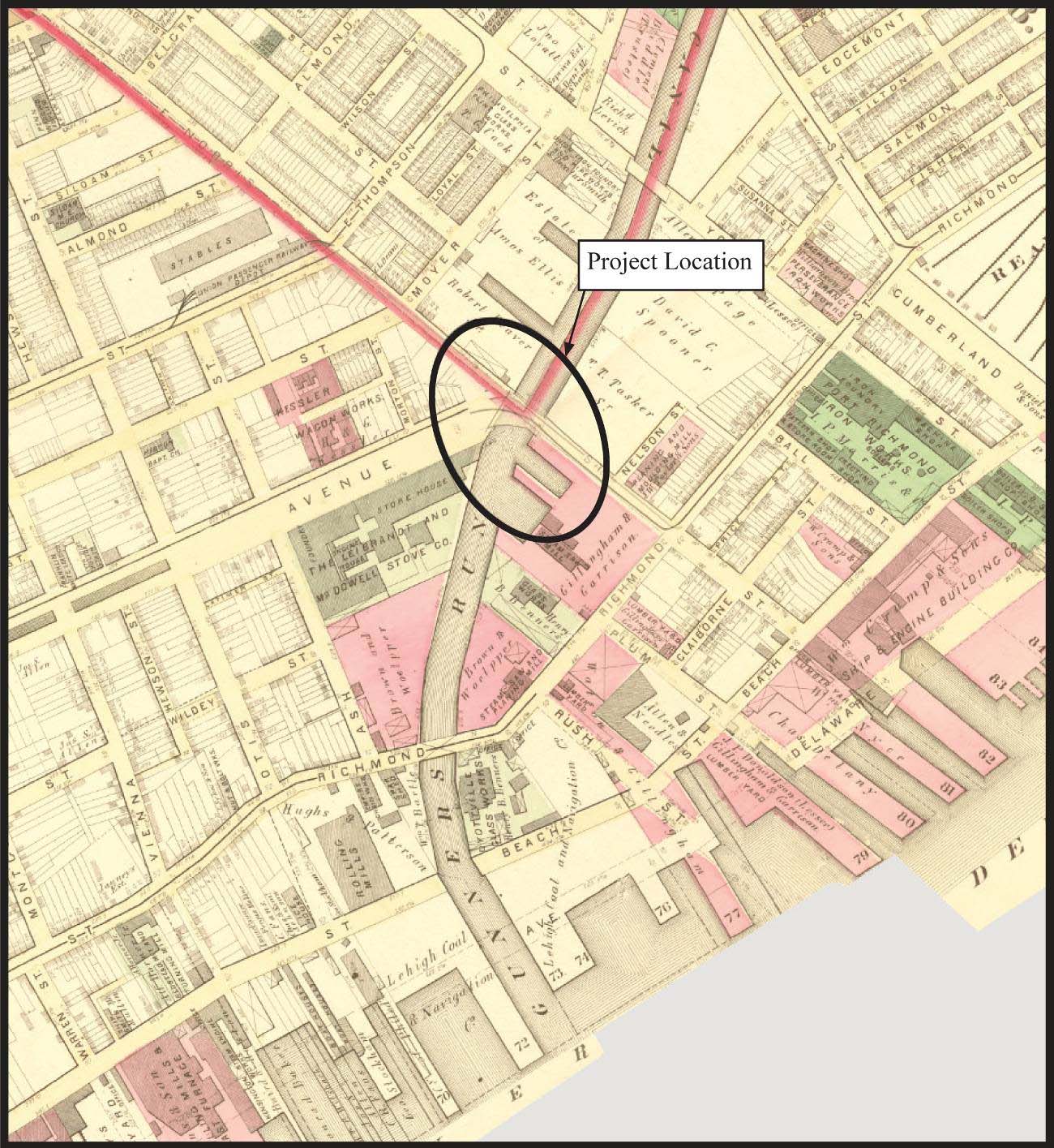
According to the Sidney (1849) map, the Aramingo Canal at the location of the data-recovery excavations was constructed to the south of the meandering Gunner’s Run channel (see Figure 2.9). Maps dating to 1862 and 1875 show the completed canal (see Figures 2.13 and 2.14). No buildings are shown at the location of the data-recovery investigations on these maps, but a sawmill is depicted nearby. The 1875 map shows Gillingham and Garrison as the owners of the property, which contained a single building labeled as a steam sawmill.
The Hopkins (1875) city atlas shows two inlets within the Gillingham and Garrison property, at the location of the data-recovery excavations, with the company’s steam sawmill fronting on those inlets. However, no inlets are shown on any earlier map of the vicinity. Historical information indicates that company’s original sawmill burned to the ground on June 23, 1871, with a total loss estimated at $40,000.00 1. It appears that the inlets off the canal were likely added when Gillingham and Garrison rebuilt their lumber business in the aftermath of the fire. A review of historic maps available through the Greater Philadelphia GeoHistory Network web site (www.philageohistory.org) indicates that the earliest commercially available maps depicting the presence of these inlets appeared in 1875. Although some later maps show only a single large inlet into the Gillingham and Garrison property, the vast majority of city maps produced between 1875 and 1895 do illustrate the presence of two distinct inlets of slightly differing sizes. Unfortunately, the Phase III excavations did not extend far enough to the south to collect any archaeological information related to the precise form of the inlets the firm constructed.
.")
A portion of the Gillingham and Garrison Mill in 1878 (Source: Hexamer 1878).
A portion of the Gillingham, Garrison, and Company mill is shown on a Hexamer general survey map of the Dyottville Glass Works (Figure 5.1). The mill is a two-story brick building with a slag roof and one-story frame extensions on the south and east walls. A logway is shown at each end of the building, suggesting that logs were floated in the inlet before being brought into the mill building. Sawn lumber would have been removed from the opposite end of the building and stacked in the open area near the second, smaller inlet. Other buildings on the property included two tool houses and a three-story brick office building with one-story additions. A gate is indicated along Richmond Street. The Hopkins (1875) 2 and Baist (1895) 3 maps show a second building to the west of the sawmill; this building may be off the edge of the Hexamer map. No major changes in buildings are shown on maps dating to the 1880s or 1890s, although the 1895 map labels the location of the data-recovery investigations as simply “Lumber Yd.” (see Figure 2.21).
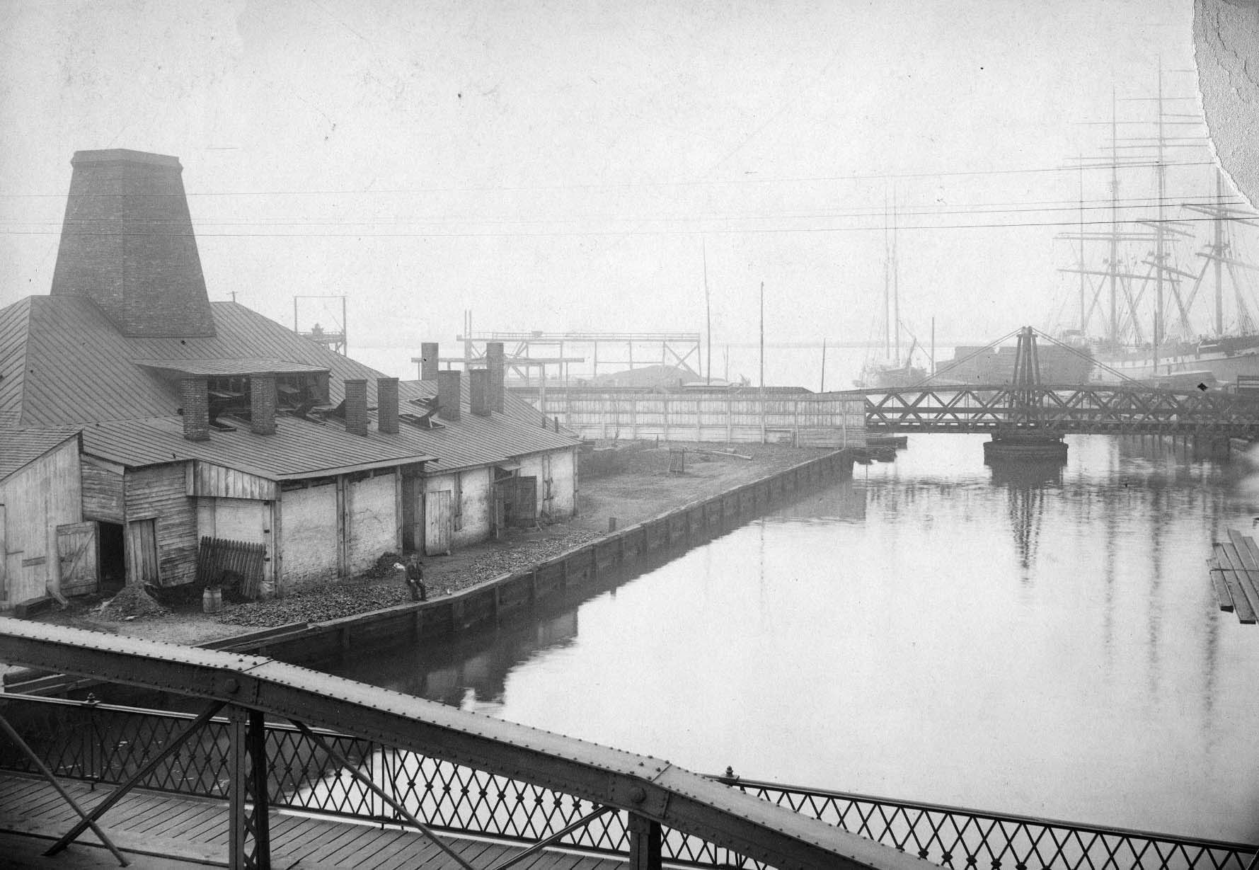
 with portions of the new Cramp machine shop superstructure in the background (Source: Philadelphia Water Department 1900–1902).")
Construction of the Aramingo sewer south of Norris Street (June 7, 1900) with portions of the new Cramp machine shop superstructure in the background (Source: Philadelphia Water Department 1900–1902).
By the turn of the twentieth century, the William Cramp and Sons Ship and Engine Building Company owned the Gillingham and Garrison property, which was the site of major development. Cramp’s shipbuilding business began in 1830 and eventually became the vicinity’s largest employer. Its early operations were located along the Delaware River at East Susquehanna Avenue and, later, Palmer Street, where wet and dry docks were present. Other facilities related to the shipyard were found in locations extending away from the water front. In 1902, Cramp, the author of a history of the family business, describes a “new” machine shop extending along Norris Street from Richmond to Dyott Streets, measuring 333 feet in length and 142 feet in width 4.
.")
Lithograph of the Cramp shipyard complex in 1919, showing the project area vicinity as it appeared following the removal of the Aramingo Canal and its replacement with new surface streets (Source: Cramp 1919).
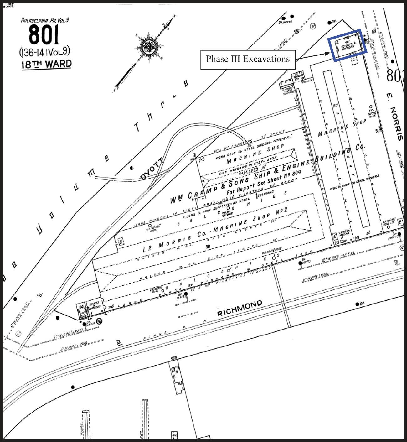
This building is likely the one shown under construction in a photograph taken as the last Aramingo Canal remnant (south of Norris Street) was being converted into a sewer (Figure 5.2). The 1919 Sanborn map (see Figure 4.6) shows the Norris Street machine shop and a rectangular extension at its west end labeled “Toilets & Lockers,” the brick-and-concrete foundation of which was identified in the data-recovery investigations. This same extension is depicted in a 1919 birds-eye view of the entire Cramp complex, which shows that buildings associated with the shipyard completely covered the remaining areas of the block bounded by the canal (now Dyott Street), Richmond Street, and East Norris Street (Figure 5.3).
Aramingo Canal, Structure, and Materials
Historical records do not describe in any specific detail the methods used to excavate the canal channel within the Gunner’s Run stream bed, nor did the archaeological investigations generate any information relative to this process. However, the investigations did provide detailed information on the overall appearance and structure of the canal, and about the materials and structure of the timber wharves that framed the canal at this location. The picture that emerges from this research is that the Aramingo Canal was, in both form and function, very much unlike the vast majority of canals constructed in Pennsylvania during the nineteenth century. In large measure, these differences stemmed from an alternate conception of what the Aramingo Canal was meant to be. While most other canals constructed in Pennsylvania and surrounding regions served as linear highways for moving raw materials, finished goods, and people over extended distances—and for connecting regional economic centers with far-flung interior areas—the Aramingo Canal was always more localized in scope. From the beginning, this canal seems to have been intended to function essentially as an inland extension of the Delaware River waterfront and the Port of Philadelphia.
Comparison to Other Pennsylvania Canals
In nearly all aspects, the Aramingo Canal was quite different from the many other canals constructed throughout the state during the nineteenth century. Canals built in Pennsylvania during the early and mid-nineteenth century exhibited a variety of specific forms and methods of construction, making a comprehensive comparison difficult. However, a general comparison with one series of canals, those of the Pennsylvania Main Line Canal system through the central sections of the state, may serve to sufficiently illustrate these differences.
Canals in this state were comprised of a variety of distinct elements, including locks, basins, dry docks, and other specialized features; however, their main component consisted of relatively simple earthen ditches filled with water. Designed, in a sense, like surface roadways, these ditches were intended to allow for the linear movement of vessels between distant points, and as such were built with fairly narrow, confined channels. Typical sections of the Pennsylvania Main Line Canal—for example, those of the Juniata Division—were constructed with a prism measuring approximately 40 feet in width at the water line, and carried a more or less constant volume of water some 4 feet in depth. The side walls for these channels were made of sloped earth, extending approximately 2 feet above the water line, and doubled as tow paths for the mules or other animals that pulled boats along the canal channel.
.")
Canal cross sections showing examples of rampering, punning, and puddling construction techniques (Source: Dzombak 1995).
Depending on the specific terrain and subsurface circumstances involved, the prisms of the Main Line and other canals were made watertight by means of a combination of common techniques, including rampering, punning, and puddling (Figure 5.4). Rampering was a means of forming stable interior banks for the prism in instances where the sidewalls of the canal needed to be artificially elevated above the natural ground surface. This method involved the emplacement of stepped blocks of cut sod, laid grass side down and beat down tight (“trampled”), along the inner edge of the banks. This served to prevent both the erosion of the embankments and to protect them against damage from burrowing animals. The act of punning is defined as a method “to consolidate by pounding” and involved the manual compaction of soils along the inner surface of the canal prism to make it impermeable and resistant to erosion. Lastly, puddling involved sealing the prism through the application of a fine-grain clay lining. This lining could be placed directly to the interior surfaces of the canal and/or could be formed within a “puddle ditch” excavated vertically within the canal embankments.
.")
Representational cross sections comparing the dimensions and construction of the Pennsylvania Main Line Canal with the Aramingo Canal (Source [Main Line image]: Wirth 1985).
Given this different physical setting, alternate engineering methods needed to be employed in the Aramingo Canal’s construction. By, in essence, converting an existing stream into a canal, the builders probably did not have to worry about employing techniques to make the bottom of the prism watertight. Because the Aramingo was intended to be used in much the same manner as the Delaware River—providing for the transport of goods and raw materials to the businesses established along its banks—the outer margins of the canal were constructed using the same technology as the nineteenth-century wharves that bounded adjacent parts of the riverfront. Timber crib wharves were installed to define the sides of the canal and to provide a platform for the loading and unloading of goods and raw materials. The interior of these cribs were filled with a dense soil matrix to anchor the wharves into the ground and to make them watertight. As such, these crib wharves can be seen as the functional equivalent of the “puddle ditch” used in the building of more traditional canals throughout other parts of Pennsylvania. The following sections provide more detailed analyses of the construction of specific elements or attributes of the Aramingo Canal.
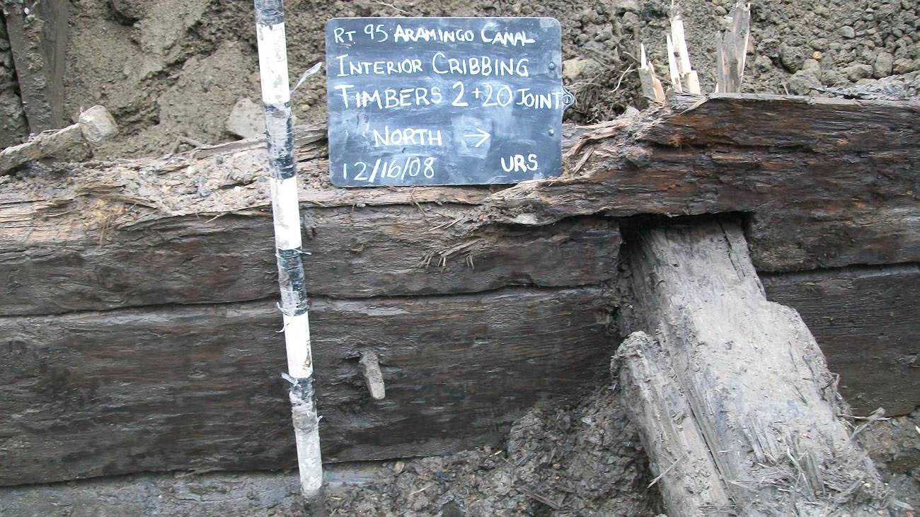
Timber Crib Wharf Construction
As described in Chapter 4, the timber canal structure uncovered during field investigations was a cribbed structure with two parallel walls built of log beams called headers. The walls were connected via crossbeams, or stretchers. Crib wharves have been built for centuries, and throughout far-flung parts of the world. For example, Heintzelman 5 notes that a crib wharf dating to the second century A.D. was identified in excavations at the Custom House Site in London, England. Two types of cribs were common. Open-crib construction utilized alternating headers and stretchers, leaving openings between each course of logs (Lincoln Log–type construction), with the interior filled with large rocks or cobbles. In contrast, the solid crib incorporated header courses arranged tightly together, with the interior of the crib filled with mud or sand. As detailed below, the wharves of the Aramingo Canal were built with an open-crib construction on the land side (interior) and a solid-crib construction on the

Rectangular timbers on the water side of the wharf showing tool marks.
water (canal and inlet/exterior) side. Material used to fill the crib in this instance consisted of a thick silt or silty clay that served to prevent water from leeching out of the canal channel. Although crib structures were often built with formal wooden floors, no evidence of a floor was identified in the data-recovery excavations (see Figure 4.16). Stones or rocks were sometimes used to sink a floored open-crib structure into the water. This type of structure is known as a cobb wharf. However, as indicated on the Sidney 6 map, the Aramingo Canal at the location of the data-recovery excavations would have been outside the meandering Gunner’s Run stream bed, on what would originally have been fast-land, so that sinking of the crib structure would not have been necessary.
 attached to the exterior crib wall.")
Vertical supports (spiles) attached to the exterior crib wall.
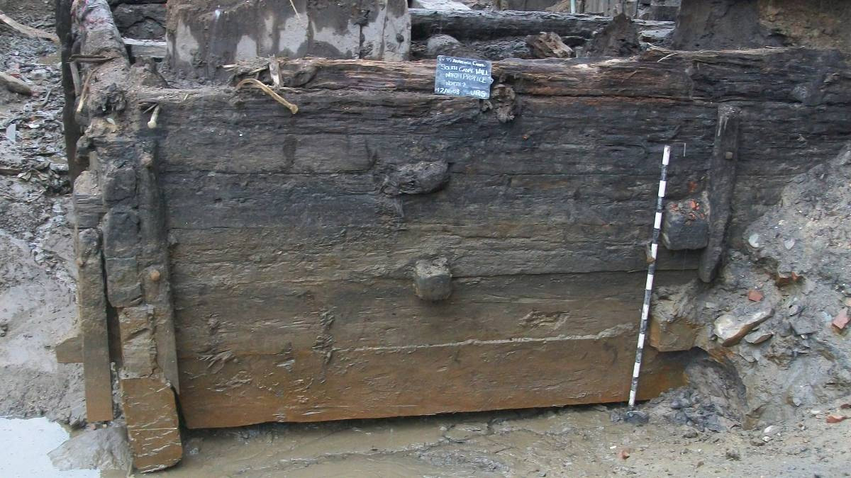
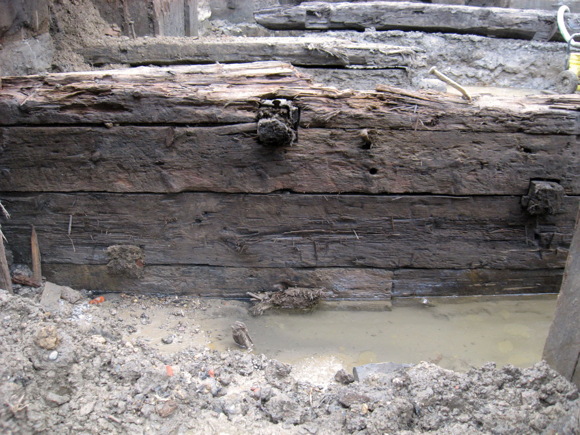
The walls on the canal and inlet sides (exterior) of the wharf uncovered during the data recovery were tightly built of rectangular timbers, characteristic of a solid-crib structure (see Figure 4.29). Tool marks were present on the rectangular timbers, indicating that they were either hewn or sawn with additional hand trimming (Figure 5.6). Vertical timbers (spiles) were placed at intervals to provide support and maintain the vertical alignment of the headers (Figure 5.7). Heintzelman 7 notes that vertical members were often added to the exterior faces of wharves to provide added support and to serve as fenders or rub rails. Historic images (see Figures 2.10 and 2.12) do show that similar vertical elements were original features of the Aramingo Canal and may have served a similar function. Both the findings of this investigation and surviving photographs indicate that the spiles used in the construction of this canal were not comprised of individual vertical timber members, but rather consisted of paired upper and lower elements that overlapped slightly near the middle of the canal wall (Figure 5.8).
 and detail showing the arrangement of spiles on the exterior/water side of the wharves (Source: Philadelphia Water Department 1900–1902).")
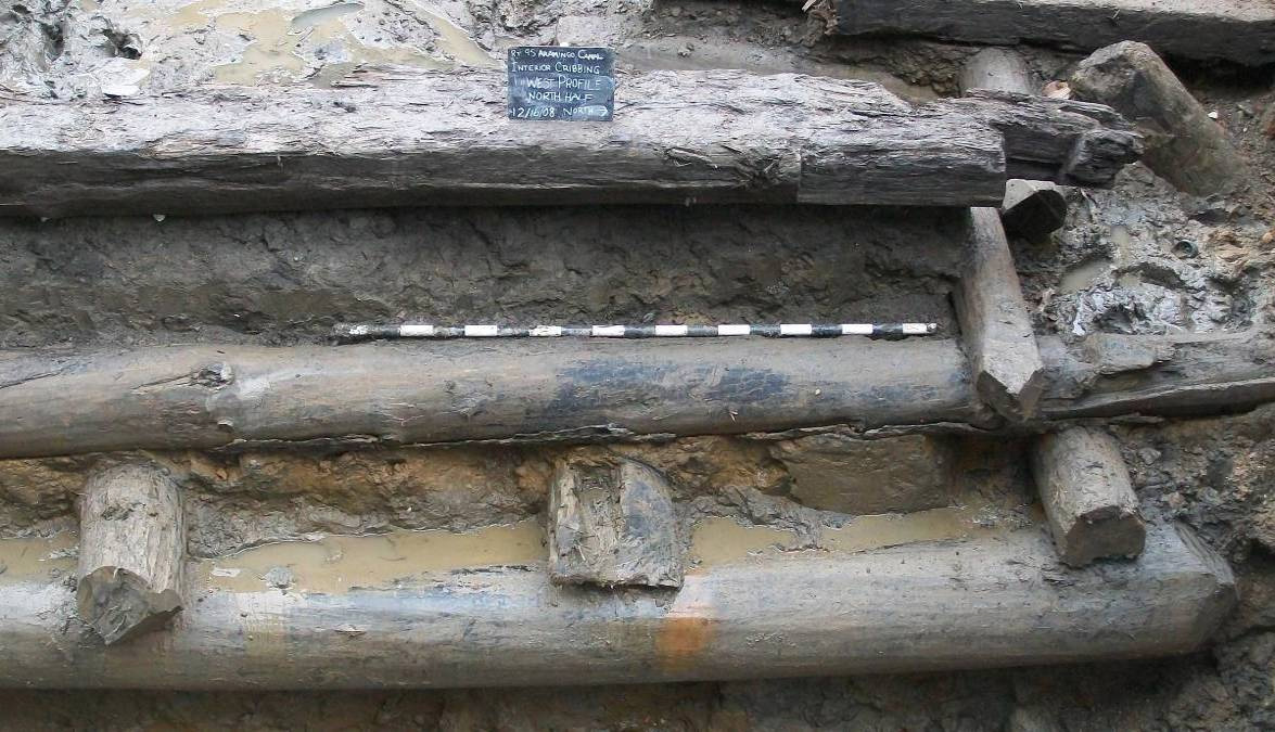
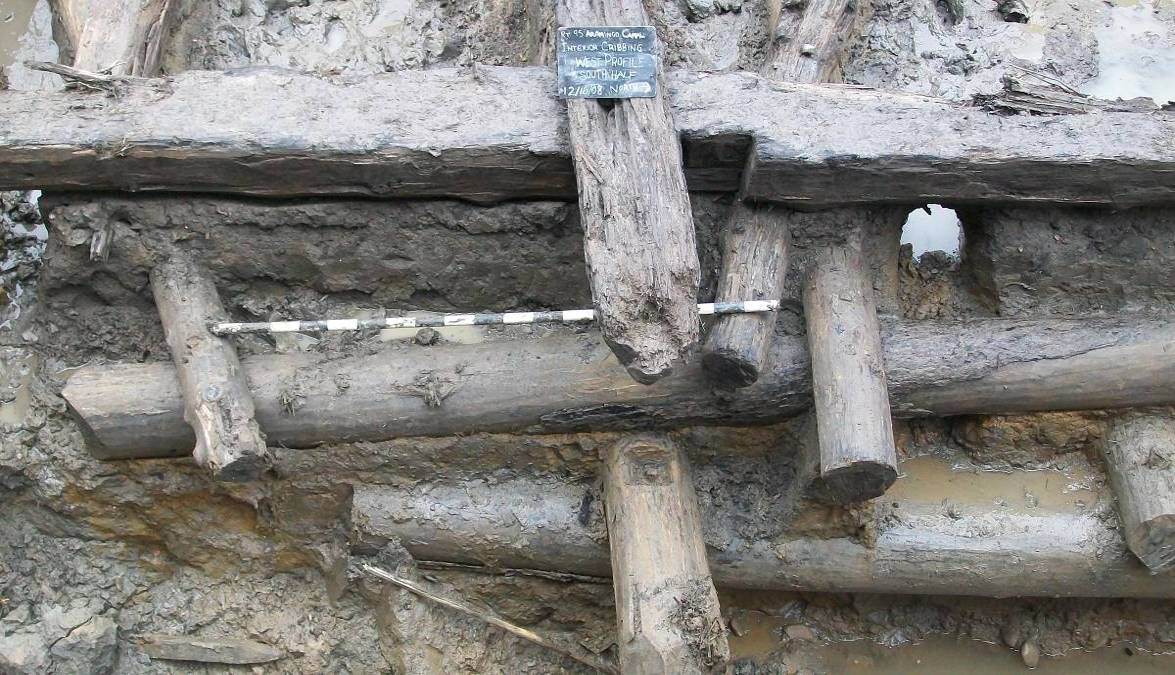
The interior, or land-side, portions of the wharves were built in a manner characteristic of an open-crib structure (see Figures 4.18 and 4.19). Data from the excavation indicates that the far eastern wall of these wharves stepped outward toward the bottom, so that the base was wider than the top of the crib. While the exact reason for this configuration is unknown, it may have been adopted to give the crib structure added strength prior to being filled with soil, and before the low ground bordering the former Gunner’s Run stream could be filled to the level of the new wharves. Some of the headers on the interior wall were rough logs with little or no trim, whereas others were trimmed and rectangular in cross section. Heintzelman (1985a) notes that barked timbers are more resistant to wood borers and other aquatic pests, but the rough logs in the Aramingo Canal structure appear to have been cleaned of bark prior to use.

Detail of headed iron bolt joining header and stretcher courses in the open portion of the crib.
Many, but not all, of the joints in the open portion of the crib were secured with iron spikes or bolts (Figure 5.9), with the specific use of these fasteners appearing to occur in a random rather than systematic pattern. No evidence was found that trunnels (treenails) were used for any aspect of construction. Hearding 8 reports on experiments that indicated the importance of headed bolts in providing long-term stability to crib structures. All of the iron fasteners identified within the Aramingo Canal wharves were headed. In several locations on the interior crib wall, recesses were cut into logs where the bolts were placed (Figure 5.10). The purpose of this technique is unclear, since the recesses were not in areas of tight construction that would require the heads to be inset.

Examples of bolts in recesses.
A closer inspection of the Aramingo wharves indicates that they were constructed in a straightforward, workmanlike manner, and employed a limited variety of relatively standard techniques to join individual timber wharf members to one another (Figures 5.11 and 5.12). The header logs used to form the exterior (water-side) faces of the wharves were joined end to end using simple butt joints, with individual joints aligned at staggered locations. Long iron spikes were driven vertically through these headers to help bind successive courses together and give the whole face greater rigidity and strength. The corner between the exterior canal and inlet walls was constructed with saddle notches, with notches having been cut into both the upper and lower surfaces of each timber in a Lincoln Log–style configuration (Figure 5.13). Vertical braces were attached via metal bolts to reinforce the exterior of this corner, and likely also served as a fender or bumper. The interior, open portions of the crib were attached to the exterior faces by means of stretcher courses and common housed saddle-notch joints (Figures 5.14 and 5.15). In some instances, iron spikes or bolts were used to reinforce these joints.

Exterior corner of inlet and canal walls.
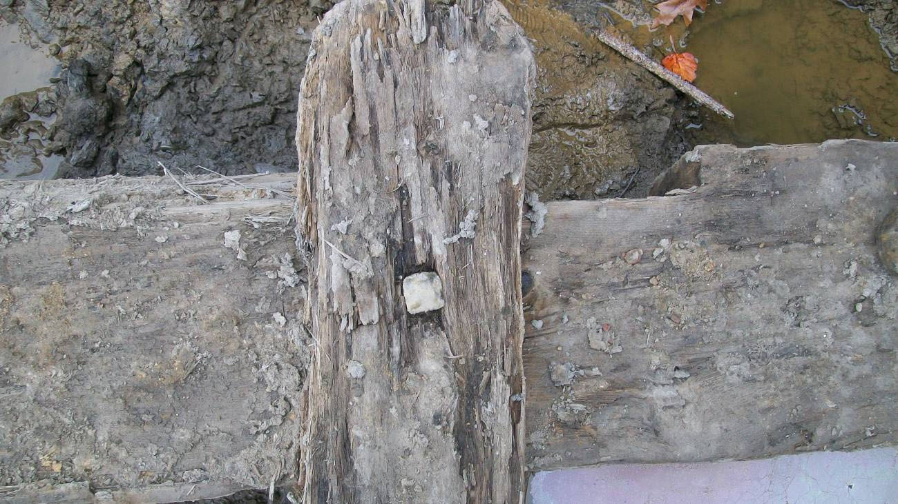
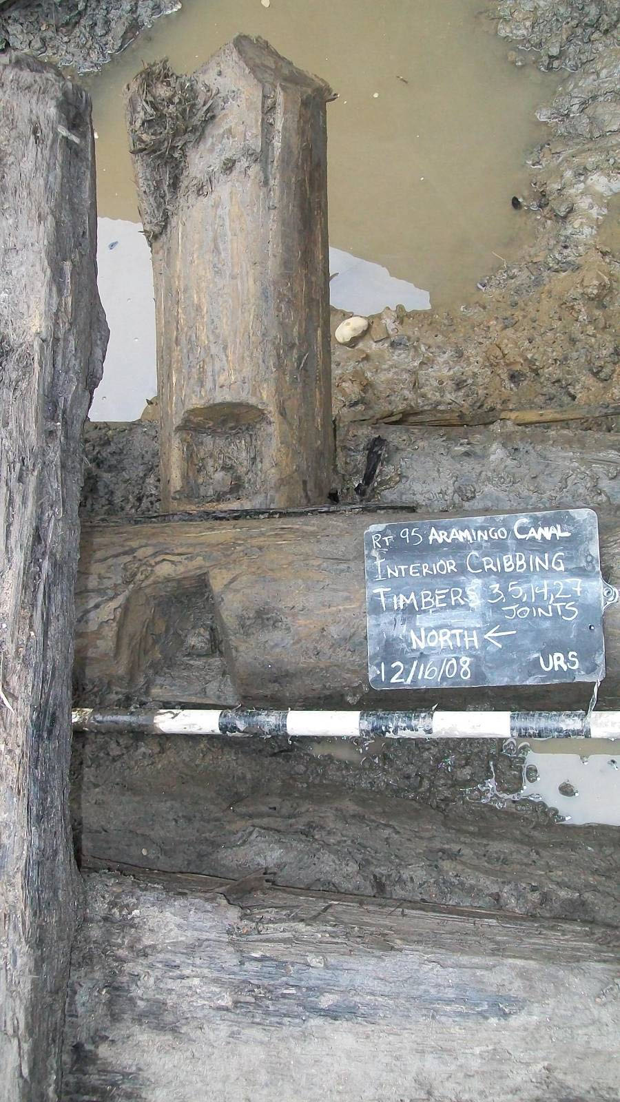
Several empty notches were present on both sides of the uppermost interior crib header (Figure 5.16). However, one lateral notch retained the remains of a vertical post; the cut bottom of the post was just below the header. These findings indicate that vertical support posts were once placed at intervals along both the inside and outside of this upper header, and may have been used to help anchor the structure into the ground, or possibly to support a now-vanished plank deck/walkway along the top of the canal.

Lateral notches on interior header. Note that the notch at right contains a cut section of vertical post.
The water-side, or exterior wall, of the Aramingo Canal is similar in construction to a number of both still functioning and archaeologically documented eighteenth- and nineteenth-century wharf bulkheads located in Philadelphia and throughout the East Coast. The Richmond Coal Wharves were a mile-long stretch of Port Richmond waterfront where coal from Pennsylvania mines was loaded onto ships 9. The original wharves were constructed in 1841 and expanded as increased shipping capacity was needed. Built by Philadelphia and Reading Rail Road, the wharves eventually extended up to Allegheny Avenue. An extant bulkhead wall at Allegheny Avenue is similar to the western wall of the Aramingo Canal crib structure (Figure 5.17).

The existing Allegheny Avenue Wharf.
Another example is the early-nineteenth-century wharf bulkhead identified during archaeological investigations of the Hertz Lot/West Shipyard Site (36PH28), located between Callowhill and Vine Streets in the Northern Liberties section of Philadelphia 10. The early-nineteenth-century wharf bulkhead was a seven-course timber structure of pine logs held together with common scarf joints and iron fastenings. Cross-ties, used to anchor the wall, were emplaced at various locations using joints like those of the housed saddle notches in the Aramingo Canal wall. The interior of the wharf bulkhead was less well finished than the exterior, but much more so than the interior of the Aramingo Canal wall. Two earlier bulkheads were also found during those excavations, dating to the 1760s and later eighteenth century, respectively. Both were constructed of logs with little trim and joined using half lap joints. Cross-ties and a metal pin were found in the earlier wharf, and a trunnel was found in the later structure. Both appear to have been built of pine.
The eighteenth-century Keith’s Wharf bulkhead in Alexandria, Virginia, was also similar to the exterior Aramingo Canal crib wall 11. As at the Hertz Lot, the Keith’s Wharf bulkhead was joined via half lap or scarf joints, rather than butt joints. Tieback braces took the place of stretchers and were used to anchor the walls; they were joined to the bulkhead with housed saddle notches. Several of the tieback braces oriented at non-perpendicular angles similar to those of some stretchers used in the Aramingo Canal crib.
Derby Wharf is the longest of three eighteenth-century wharves built in SalemHarbor 12. It was constructed in 1762 of rectangular timbers laid with random butt joints. Spiles and tiebacks were used to strengthen and anchor the bulkhead. Two parallel bulkheads were built into the harbor at low tide and filled between with mud and stone. At one time, the wharf had almost 20 structures built on it. In the nineteenth century, the wharf was encased in large granite blocks.
Timber cribs have been used for the construction of both wharves and breakwaters. The Carlyle Dalton Wharf in Alexandria was a crib structure built circa 1760 13. Excavations at that site exposed timber cribbing similar to that of the eighteenth-century wharves at Hertz Lot. The wood was yellow pine with the bark intact. The logs were joined with housed saddle notches. One trunnel was identified.
The Aramingo Canal crib construction was similar to the oldest phase of the Plattsburgh Breakwater, located on Lake Champlain in the city of Plattsburgh, New York 14. Construction began in 1836 and the breakwater reached to a length of 846 feet by 1844. This early portion of the breakwater consists of both round and square logs, with saddle notch joints at the corners and random butt joints on the wall. Hemlock was used below the water line and pine above. The breakwater was filled with cobbles and covered with capstones.
The Burlington Breakwater in the city of Burlington, Vermont, was a timber crib structure [15. United States Army Corps of Engineers and New York District (USACE) (2010). Burlington Breakwater–City of Burlington, Vermont]. Burlington is located across Lake Champlain from Plattsburgh and construction of the two breakwaters began in the same year. The first phase of construction was completed in 1854. The cribbing in the initial construction phase was comprised of round and squared hemlock, with the upper 7 feet built of pine. Each crib was approximately 100 feet long and rested on a stone or rubble base. As is the case with the Aramingo Canal wharves, the cribs of the Burlington Breakwater were wider at the bottom than at the top. These measured 50 feet wide at the base and tapered to 35 feet wide at the water surface, with a vertical face on the lakeside. The cribbing from the initial construction phase was open and filled with cobbles and capped with granite stones. The crib structure reached a height of 8 feet above the low-water mark. The Burlington Breakwater is listed on the National Register of Historic Places.
Depth of the Canal
Efforts to try and determine reasonable estimates for the overall depth of the Aramingo Canal involves solving two separate yet interrelated issues:
- The height of the timber wharves bounding the canal.
- The depth of water carried within the canal.
Unfortunately, no surviving historical accounts have been identified that shed light on either of these questions.
With respect to the first issue, these archaeological investigations revealed that the wharf forming the eastern wall of the canal was at least 8 feet in height; however, it was also clear from the excavation findings that some of the uppermost wharf timbers had been removed in the past to allow for the installation of the foundations of the Cramp “Toilets and Lockers” extension. Additional insight into the total wharf height may be contained in the species identification for wood samples taken from the crib timbers. Those findings identified that two of the uppermost surviving timbers were pine, while all of the sampled lower members were hemlock. Historic information pertaining to wharf and breakwater construction note that hemlock logs were frequently used for sections of these structures below the water line, and that pine was most often used for above-water sections. If similar construction methods were used for the Aramingo Canal, then the archaeological findings suggest that the timbers removed during Cramp construction corresponded to those sections that originally extended above the water line of the canal. Surviving historical photographs, maps, and other images all seem to indicate that the canal’s wharves did not extend more than a few feet above the water. This makes sense, in that wharves that extended a considerable height above the water would have made the loading and unloading of goods and/or raw materials from canal boats more difficult. Putting all this information together, it seems reasonable to suggest that not more than 2 or 3 feet of the wharves were removed during construction of the toilets and lockers extension, and to propose that the original maximum height of the wharves was likely somewhere around 10 to 12 feet.
Determining the depth of water in the canal is problematic as well, largely because water levels in the canal were evidently subject to daily tidal fluctuations. Original conceptions of the canal, as outlined in the 1847 Gunner’s Run Improvement Company’s act of incorporation documents (Appendix A), called for the construction of a tide-lock or tide-gate at the mouth of the canal, which would have functioned to keep water levels in the canal constant regardless of tide stages in the Delaware River. However, no historical evidence has yet been found to confirm that such a structure was ever built. Hard data regarding the extent of tidal variations within the canal was recorded in 1896 by the Philadelphia Bureau of Surveys, as that agency was studying the effect of tides on the flow rate of water within tidal sewers 15. In the late fall of that year, engineers completed a series of readings for the new Aramingo Sewer, at the (then) sewer outlet into the canal at Norris Street (as noted in Chapter 2, as of 1895 the partially abandoned Aramingo Canal terminated at Norris Street). Readings of the level of water within the mouth of the sewer documented a maximum high to low tide fluctuation of about 6.5 feet.
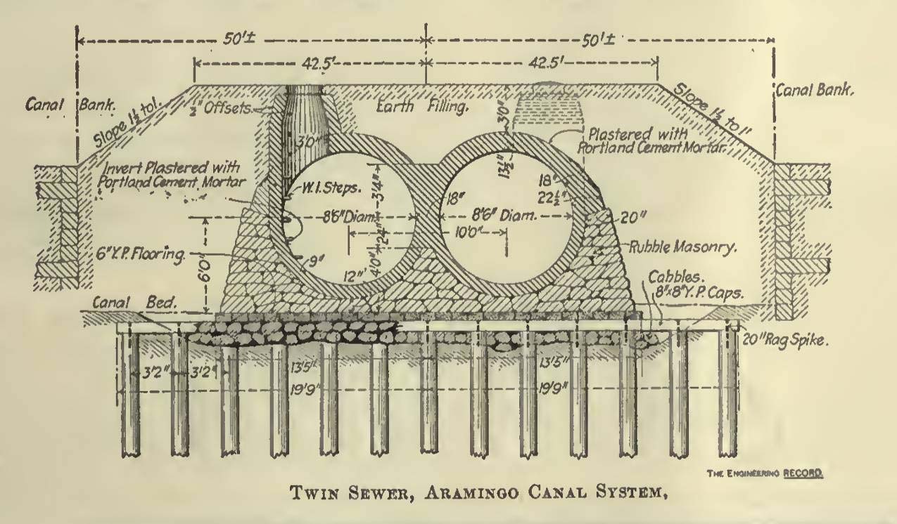
Information contained in the Philadelphia Bureau of Surveys report is helpful in allowing reasonably accurate estimates to be calculated regarding the maximum and minimum levels of water carried via the canal during its years of operation. The level of tidal water in the sewer was recorded as varying between roughly 1 and 7 feet deep, as measured relative to the 8-foot diameter sewer cavity. From engineering specifications for the Aramingo Sewer (see Figure 2.23), the interior top of the sewer conduit was built at a height of approximately 10 feet above the bed of the canal. Using the Bureau of Surveys readings, then, it can be estimated that at high tide, the Aramingo Canal would have contained a volume of water measuring somewhere in the vicinity of 9 feet deep. This calculation matches up reasonably well with information gleaned from the wharf timber species identification analysis discussed above, which suggested that high-tide water levels in the canal were about 8 feet deep. Given the tidal fluctuation documented by late-nineteenth-century city engineers, it would appear that water levels in the Aramingo Canal likely cycled daily between roughly 9 and 3 feet in total depth.
Canal Bottom
Heintzelman 16 notes that where the bottom material below the crib is gravel, stone, or rubble, the wharf remained stable. The data-recovery investigations encountered what could have been either stream cobbles or glacial outwash till contained in a reddish clay matrix, which was likely sufficient to maintain the stability of the structure. Although groundwater and the constant slumping of canal fill material hampered detailed assessment of these basal deposits, no evidence was found to indicate that the bottom of the canal prism was prepared in any way—by means of common punning or puddling techniques, as two examples. Even if the bottom of the canal prism had been formally prepared when originally constructed, the driving of piles during the sewer conversion process would have destroyed any evidence of such a treatment.
Use and Abandonment of the Canal
As part of the data-recovery investigation, it was hoped that background research would uncover historic accounts and records that would provide more detailed information regarding the operation and use of the Aramingo Canal, as well as about its impact on the development of the surrounding area. Unfortunately, no thorough or comprehensive documentation relating to these issues could be located in area archives, and it is unknown whether or not any records—even rudimentary accountings of the types or amounts of goods moved in or out on the canal—were ever kept. Instead, only the few trace records and spare reminiscences related in Chapter 2 of this report have survived. Despite this absence of detailed information, some new insights into the functioning and use of the Aramingo Canal can be gleaned from a consideration of several factors related to the overall form of the canal and associated structures. In particular, these issues suggest that there were a number of serious drawbacks to the design of the canal that may have critically restricted its intended function and use, and ultimately doomed its long-term economic viability.
.")
Lithograph showing small sail-rigged ships in the canal near the Dyottville Glassworks, between Richmond and Beach Streets (Source: Easton 1858).
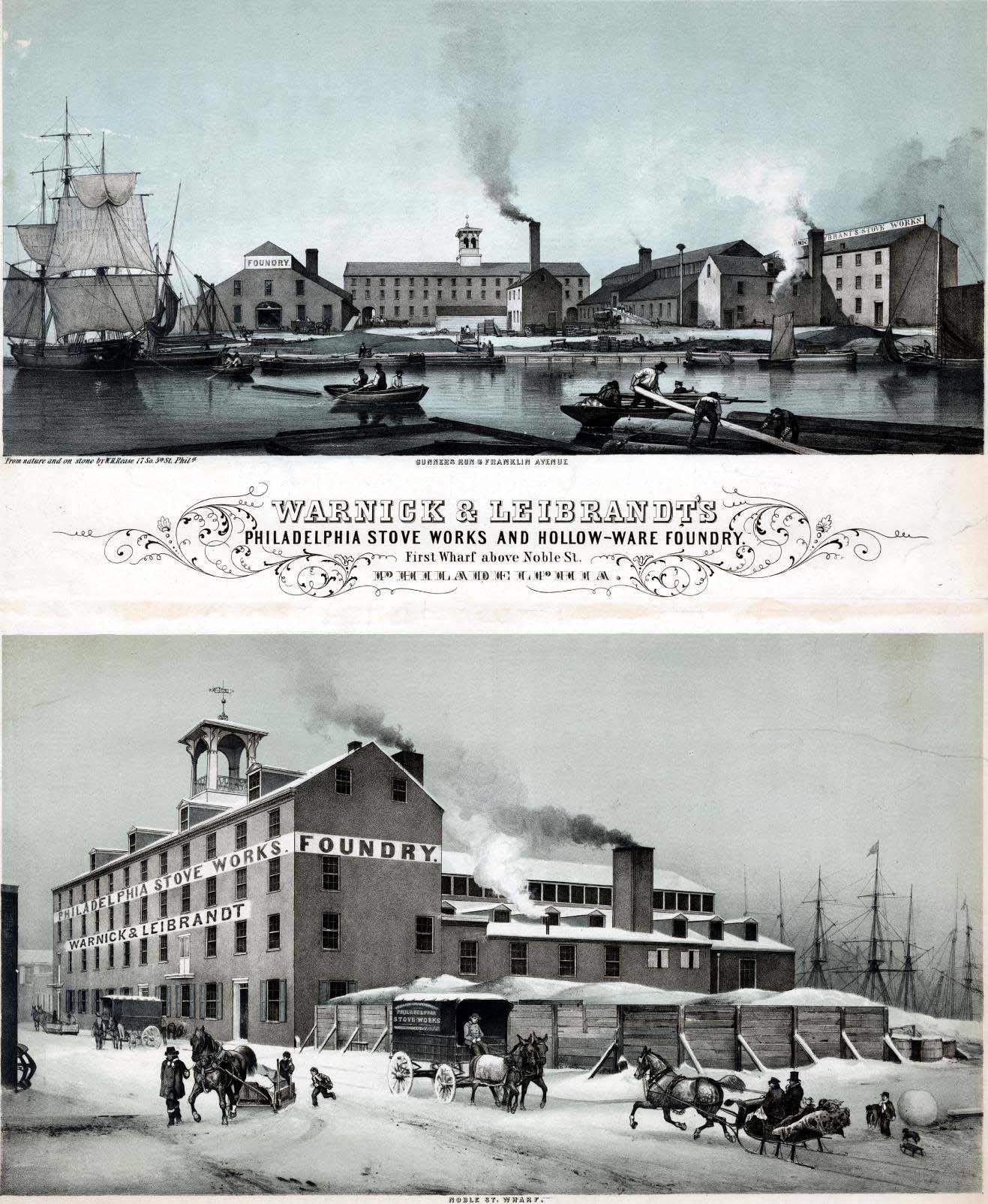
There are a number of tangential pieces of information that suggest that, during its heyday, from the early 1850s through the mid-1870s, the Aramingo Canal was quite a busy place. Printed reflections of the canal’s history stated that in these earlier years, boat and ship traffic on its waters was quite heavy, with a variety of different vessel types, including schooner-rigged sailing craft, flat-bottomed sand scows, and others having been known to operate there. As depicted in Figure 2.12, early advertisements carefully depict this busy aquatic activity and show a range of vessel types, from large to small, as freely operating within the canal. Other lithograph images, such as that in Figure 5.18 below, clearly show a number of smaller sail-rigged ships in the canal alongside the Dyottville Glassworks complex. The question that must be examined critically is: Just how accurately do these recollections and images portray shipping activity on the canal?
.")
Photograph of the Beach Street bridge and Aramingo Canal at ebb tide (Source: Philadelphia Water Department 1900–1902).
Two primary factors are believed to have served to significantly curtail the free use and navigation of at least parts of the canal and, in turn, would likely have kept it from ever maximizing its economic and industrial potential. The first of these issues is the tidal nature of the canal discussed above. As the Bureau of Surveys data shows, the canal experienced rather pronounced daily fluctuations in water level, and those would have almost certainly placed some limitations on the types of vessels that could have navigated these waters. At high tide, the canal’s water level was likely around 8 or 9 feet deep, and would have supported a wide variety of boats, including some of a larger size. However, at low tide, and with only perhaps 3 feet of water available, only the smallest, shallowest draft vessels would have been able to operate—and they could not have carried much in the way of cargo. To make matters worse, numerous historic accounts describe deposits of thick mud that fairly quickly collected in the bottom of the canal. As these deposits accumulated, they would have acted to further reduce the amount of water able to enter the canal at low tide, to the point that the canal may have been completely impassable during these periods. Figure 5.19 shows an image of the canal at the Beach Street bridge, at what is believed to be low tide, that appears to verify this interpretation. Because a tide-lock appears to have never been built, and without the ability to support constant free navigation of vessels, the canal was probably never as attractive to commerce as originally intended.
The second inhibiting issue relates to the bridges built across the canal. Between the Delaware River and York Street, a total of three bridges spanned the canal during its period of operation: one at the intersection of Norris Street and Girard Avenue (built prior to 1853); one at Queen (later Richmond) Street (built 1853 and rebuilt circa 1876 17); and one at Beach Street. Of these, the Beach Street bridge was probably never much of an impediment to the use of the canal. Historic documents indicate 18, and historic maps confirm, that this bridge was not constructed until sometime in the early to mid-1870s. Prior to that, no bridge spanned this location and ships would have been free and unimpeded to sail the canal at least as far up as Richmond Street. Historic photographs (see Figure 5.19) clearly show that the Beach Street bridge was of the swing (or pivot) variety, and therefore would have been able to admit larger and sail-rigged ships into the canal. Unfortunately, the same was not the case to the other bridges farther inland.
.")
Detail showing the elevation of the Richmond Street bridge above the Aramingo Sewer. Note that the Dyottville Glassworks buildings at right were constructed more or less at the level of the top of the Aramingo Canal wharves (Source: Philadelphia Water Department 1900–1902).
Surviving historic photographs taken during the conversion of the canal to sewer clearly show that, for reasons unknown, both of these structures were constructed as flat, fixed iron spans, not as draw or pivot bridges. The best images strongly suggest that neither of these bridges were elevated more than a few feet over the canal and surrounding ground surface (Figure 5.20; see Figure 3.15 for an image of the Norris Street bridge). While it is often difficult to make accurate estimates based on details in these photographs, the image of the Richmond Street bridge appears to show a maximum of perhaps 4 to 6 feet of clearance between the bottom of the superstructure and the top of the canal wharves and surrounding ground surface. Assuming a drop of a few more feet to the high-tide water line, it can be estimated that perhaps a maximum of 10 feet in vertical clearance existed beneath this bridge, and conceivably it was significantly less than that. Of course, bridge clearance would have been greater during periods of lower tide, but there also would have been less water available in which ships could maneuver. Based on the historical images available for review, the vertical clearance of the Norris Street bridge is even more difficult to ascertain. However, it would appear that the height of this structure over the canal was even less than that of the Richmond Street span, meaning that vertical clearance from the surface of the canal may have been less as well, and suggests that the Norris Street bridge likely represented an even greater barrier to the free movement of canal vessels.
The main point of examining the structure of these bridges is to draw conclusions as to whether or not they would have served to in some way limit or hinder the movement of ships and goods on the canal. It seems clear that portions to the south of Richmond Street were open to all manner of vessels that could navigate in the canal’s channel. This potentially included some forms of schooner-rigged ships, such as those described in newspaper accounts, although the navigation of larger vessels may have been restricted to periods of higher tide only. At Richmond Street, and again at Norris Street, it is difficult to see how the low, fixed iron bridges built in those locations did not place at least some restrictions on the types of boats that could pass under them. Most problematic is the issue of how any sizeable vessel fitted with fixed-mast rigging could have gotten past those spans. While it may be that ships equipped with tabernacle masts, which could be folded down horizontal with the deck, could have made it under these bridges, it is not known with certainty if such vessels operated on the canal. All in all, the available evidence seems to suggest that barriers posed by these bridges would have placed significant restrictions on the free passage and movement of at least larger vessels inland of Richmond Street. Presumably, this condition would have ultimately pressured industries located above those bridges to be, or to become, less dependent on the use of the canal for commercial purposes. If this was the case, then the long-term economic viability of more northerly stretches of the Aramingo Canal would have been severely compromised, which may help to explain why canal construction was never extended beyond the vicinity of Lehigh Street.
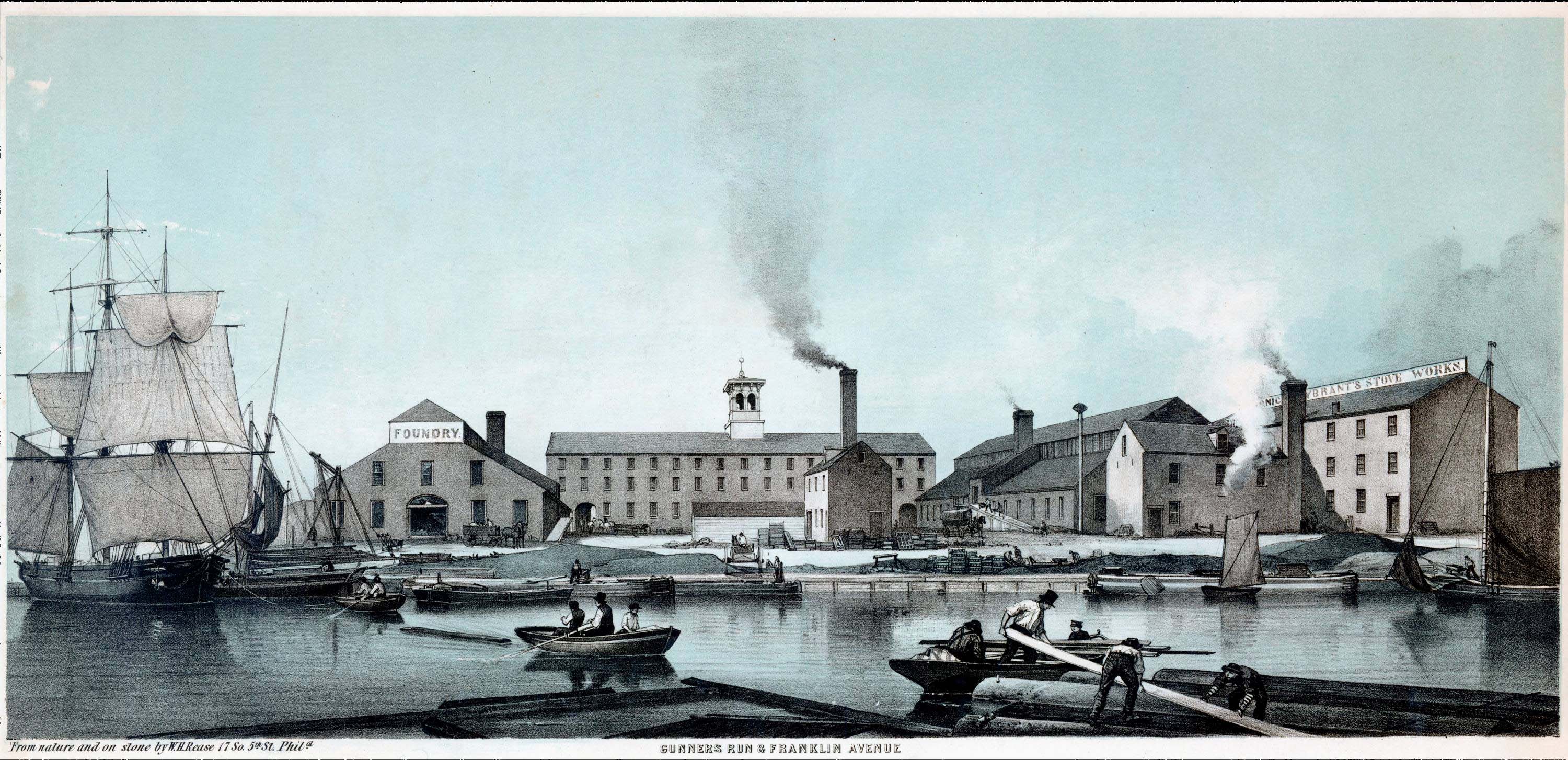
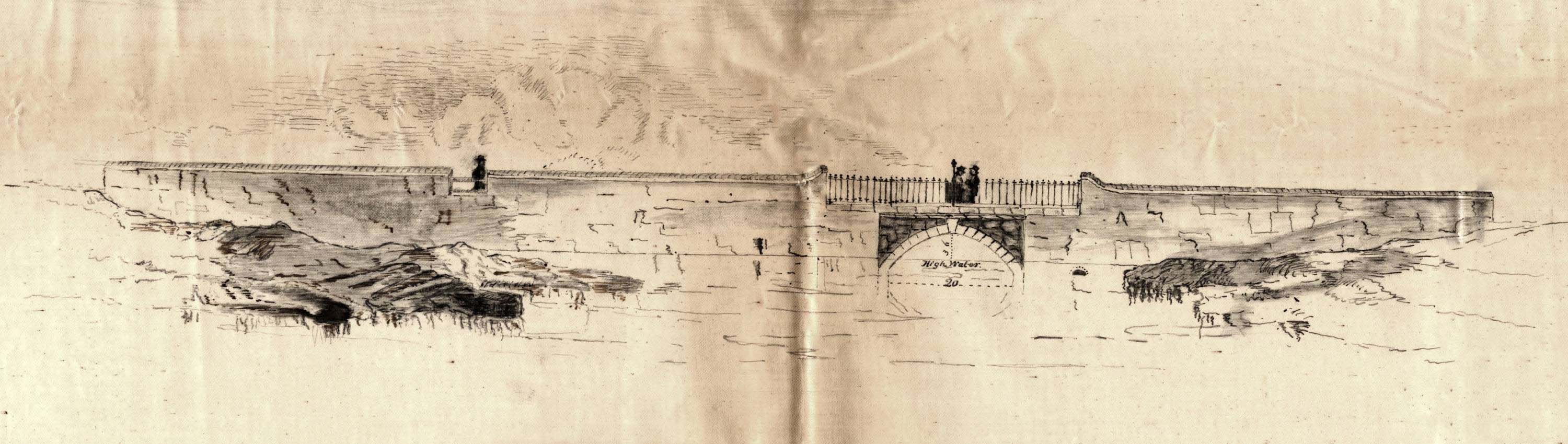
Before moving on, given the information above, it is necessary to more critically examine the image of the Aramingo Canal presented in the Warnick and Leibrandt Stove Works advertisement shown in Figures 2.11 and 2.12. Of all the historic images identified during this investigation, this lithograph is perhaps the single best and most detailed depiction of transportation and industrial activity on the canal. Although the artist purports to have created this image “from nature,” it seems that the scene portrayed is likely to be inaccurate in several ways. The image was created in 1850 and shows a variety of both large and small boats on the canal, including one fixed-rigged ship of very large proportions. The main problem here is that prior to 1853, the Aramingo Canal was not yet connected to the Delaware River. While the Gunner’s Run Improvement Company was granted permission to extend the canal to the river in 1848, that work was ultimately not completed until the existing stone bridge at Richmond Street, with a 20-foot-wide span (see Figure 2.6), was replaced in 1853 with a larger iron bridge. So the dilemma posed by this advertisement is that most of the ships shown in it could not have operated on the already finished canal sections unless they had been built on the canal itself. Even if this were the case, they would have had no place to sail to. This image was also shared with experts associated with the Philadelphia Seaport Museum in an effort to figure out what the draft would have been on the largest vessel depicted. Mr. Ed Leaf, the historian who examined it, determined that ship could have drawn up to 20 feet of water. If estimates about the canal’s maximum water level (approximately 8 to 9 feet) are correct, then a ship of this size could not possibly have operated on the canal. In the final analysis, it seems that the individual who created this advertisement employed a considerable measure of artistic license, and chose to depict the Aramingo Canal as many hoped it would one day appear, but probably never did.
As detailed in Chapter 2, the most intensive use of the Aramingo Canal was near the Delaware River, where wharves and shipyards were concentrated, and presumably where navigation on the canal itself was least restricted. Large companies located south of Girard Avenue that used the canal for shipping included lumber mills, rolling mills, a stove company, and glass-manufacturing companies. These industries appear to have relied on the canal primarily for the delivery of necessary raw materials rather than the movement of finished products out to the Port of Philadelphia and regional markets. Historic accounts indicate that the most important materials brought in through the canal included coal to power furnace and steam engines, sand for use in the production of glass at the Dyottville complex and for mold casting at the Leibrandt and McDowall Stove Works, and lumber to be processed at the Brown and Woelpper and Gillingham and Garrison Lumber Yards. While these various industries no doubt made heavy use of the canal during its mid-nineteenth-century glory days, it is not known the extent to which they may have gradually transitioned to other means for importing raw materials as problems and conditions within the canal worsened over time.
While substantial industries were established along the canal to the north of Norris Street, such as the American Brick and Fire Tile Company and the John T. Lewis Lead Works, it remains uncertain the extent to which their operations relied on the use of the canal, or how any such reliance may have changed over time. In general, industrial development along this section of the canal was substantially less dense than in sections downstream, suggesting that the canal’s presence here might not have been as beneficial to the establishment of industry. To be sure, any nuisances or difficulties caused by the canal’s tidal fluctuations or low bridge clearances would have been experienced much more acutely in areas farther inland of the Delaware River, and may have prompted businesses in this area to turn to the railroads and other alternate sources for the transportation of finished goods and delivery of raw materials.
The one industry that may have continued to profit via the Aramingo Canal throughout its brief period of operation was the lumber business the Brown and Woelpper and Gillingham and Garrison companies carried on. For both of these firms, the canal provided a critical avenue by which raw timber was transported to their mills for processing into finished boards and other products. Inherent difficulties with the canal’s operation may have less severely affected the delivery of lumber, and in some ways may have actually benefited that operation. Tidal surges moving up the canal likely served to assist with the rafting of raw timber to the saw and planning mills, and low fixed bridges would have posed less of an impediment to floating logs than it did to sailing vessels. Given its importance, the final call to close and remove the canal—made by those in the neighborhood who did not directly benefit from it—may have signaled the end of the lumber industry in this vicinity, and was likely a key factor influencing the sale of the Gillingham and Garrison property to William Cramp and Sons Ship and Engine Building Company sometime after 1895.
Aramingo Sewer Construction
Along with documentary evidence, the Phase I/II excavations to the north of Girard Avenue and the data-recovery excavations to the south of Girard Avenue provided information on the construction of the Aramingo sewer and the filling of the canal. Twin brick sewers were built within the northern portions of the canal, extending to a point 932 feet south of Girard Avenue, where the existing exterior wharves provided effective reinforcement for the surrounding ground surface 19. A single trough with concrete sidewalls and steel-girder spans was constructed at the lowermost end of the canal, where it met the Delaware River.
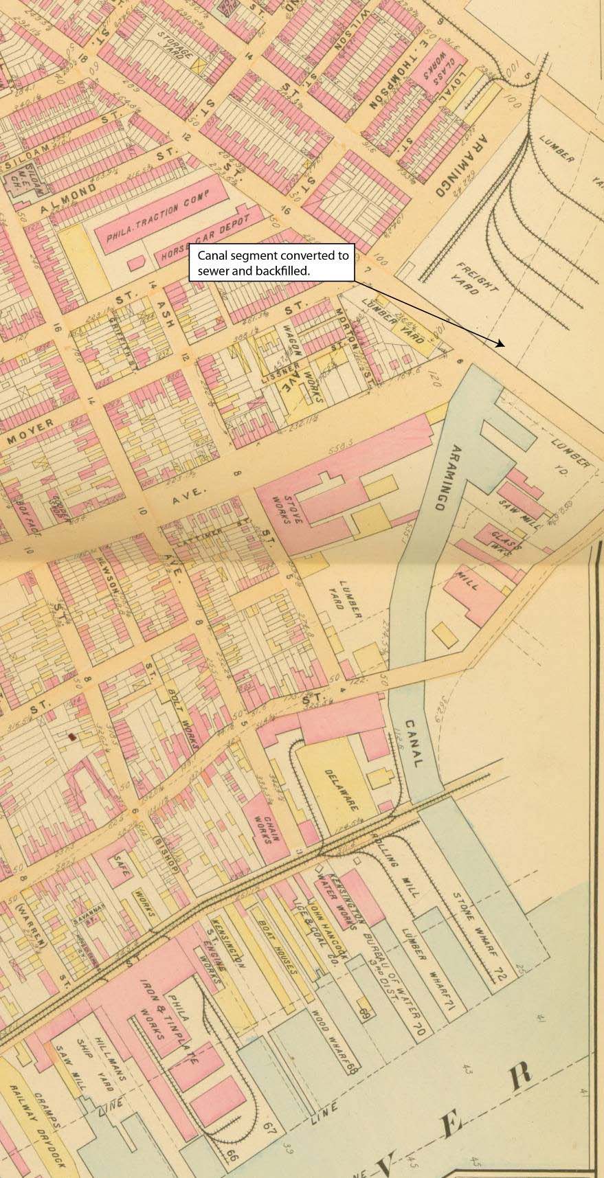
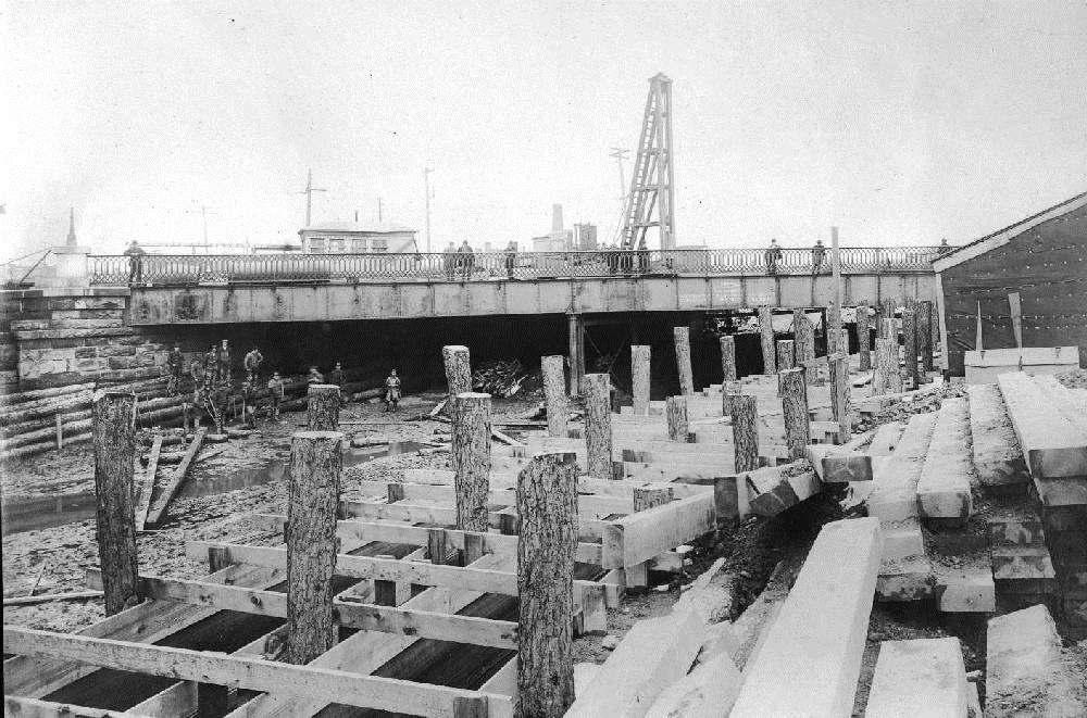
Authorization to construct the sewer and fill the portion of the Aramingo Canal north of the Girard Avenue/Norris Street intersection was issued in 1889. According to Datesman 20, work in this area began with banking of the canal sides and the ends of the sewer sections to form a mud dam, followed by driving piles into the old floor of the canal. Water was pumped to keep the area dry. Work to convert the northern sections of the canal was completed by 1895, and historic maps of the same year show the areas above Norris Street having been converted to a rail yard for the Pennsylvania Railroad. Newspaper accounts from around this time indicate that as of 1895 the Aramingo Canal only extended as far inland as Norris Street, where it terminated in a wooden “bulkhead.” The post wall structure found during Phase IB/II testing was likely an example of a coffer dam or bulkhead built at the ends of sewer sections, referred to by Datesman [zotpressInText item=”{SJ9NNFNR}”]. The fact that the vertical piles within this structure were later cut off indicates that it was intended to be temporary in nature.
Following construction of the new sewers, the former canal channel was gradually filled in with a mixture of soil, ash and cinders, and construction debris. By 1902, it had effectively been removed from the cityscape. Soon after, two new public streets—Aramingo Avenue and Dyott Street—were built over the old canal alignment.
Summary and Recommendations
The data-recovery investigations were completed in accordance with the approved data-recovery plan. The field excavations uncovered a crib structure representing the wall of the Aramingo Canal and an inlet for the Gillingham and Garrison sawmill. The foundation of a portion of the William Cramp and Sons machine shop was also revealed. Phase IB/II investigations identified a canal wall fragment and a portion of a retaining wall associated with construction of the Aramingo sewer. Both investigations encountered abutments of the Norris Street bridge across the canal. Along with documentary evidence uncovered during extensive background research, the structures identified in the field provided information to address research issues related to the construction and use of the Aramingo Canal.
The Aramingo Canal was constructed within the meandering channel of Gunner’s Run, but no specific information on rechanneling of the stream was found. The walls of the canal were of crib construction similar to many wharves of the period. The crib was a solid-crib construction on the canal/inlet side and an open-crib on the interior side; it was built of hemlock and pine. The maximum height of the extant wall was 8 feet, but estimates indicate it may have originally been some 10 to 12 feet high prior to removal of the uppermost timber members during Cramp construction. Data collected by the Philadelphia Bureau for Surveys assisted in the formulation of estimates that the canal water was tidal in nature, and may have fluctuated between approximately 3 and 9 feet in depth. There is no evidence that the bottom of the canal was prepared in any way, although groundwater hampered evaluation. Deposits at the base of the crib consisted of stream cobbles in a reddish clay matrix.
Review of the documentation on eighteenth- and early-nineteenth-century wharf and breakwater construction reveals a number of similarities with the Aramingo Canal wall construction. The canal/inlet (west) wall of the Aramingo Canal was constructed in a similar fashion to wharf and breakwater bulkheads built around the same time. Timbers were squared and tightly fit with butt joints and with spiles to maintain the vertical alignment. These structures were largely water tight and suitable for docking ships. Like many wharves and breakwaters, the Aramingo Canal crib structure was built of pine and hemlock, the latter wood having been considered well-suited for structures below water.
Large companies located south of Girard Avenue used the canal for delivery of a variety of necessary raw materials, including coal, sand, and raw timber. The companies included lumber mills, rolling mills, a stove company, and glass-manufacturing companies. The Gillingham and Garrison mill had a logway from the canal inlet to the mill building, suggesting that the presence of the canal was critical to its operation.
The canal was expensive to maintain and not used as intensively as anticipated. Sewers emptied into the canal and waste from adjacent factories further contaminated the water. Artifacts recovered from within the canal prism consist primarily of bottle glass dating to the late nineteenth century, and almost certainly were introduced during the final in-filling of the canal channel. The canal was removed from the city plan in 1889 to be filled and replaced by Aramingo Avenue following construction of the Aramingo sewer within the canal bed. A portion of a temporary retaining wall or coffer dam related to the conversion of the canal into a public sewer was identified during the Phase I/II investigations.
Phase IB/II survey covered all areas of potential ground disturbance for the GR0 section of the I-95/GIR Project that could feasibly be tested. The investigations related to the Aramingo Canal provided significant new information on the history and physical structure of the canal. The structures uncovered in the excavations were thoroughly documented through photographs and drawings. No further work in the GR0 section of the I-95/GIR Project is recommended.
As a final note, archaeological and historical information gathered during this investigation indicates that the Aramingo Canal, though long removed from the collective memory of local residents, still exists and remains more or less intact beneath the surrounding cityscape. Archaeological documentation has demonstrated that the timber crib wharf outer walls of the canal are well preserved at a depth of approximately 8 feet below the modern ground surface. These excavations have also shown that, despite its eventual conversion into a large public sewer and burial beneath city streets, the old canal still continues to carry water. Surviving documents and accounts of the canal’s transformation to a sewer show that the original timber side walls of that channel were not destroyed in that process, but rather were left in place and utilized to help frame the active work and construction space in the former canal bottom. As a result, there is good reason to believe that much, if not all, of the full canal prism, from the vicinity of Lehigh Street to the Delaware River, remains preserved below portions of Aramingo Avenue, the Aramingo Shopping Center parking lot, the I-95/Girard Avenue intersection, Richmond Street, and Dyott Street. Although some limited portions of the canal may have been damaged during subsequent construction or the installation of modern utilities, the findings from this investigation strongly suggest that the vast majority of the canal has survived in remarkably good condition.
References
- Walther (1925). Happenings in Ye Olde Philadelphia, 1680-1900 ↩
- Speirs (1897). The Street Railway System of Philadelphia: Its History and Present Condition ↩
- Baist (1895). Baist’s Property Atlas of the City of Philadelphia, Pennsylvania ↩
- Cramp, William and & Sons Ship & Engine Building Company (1902). Cramp’s Shipyard ↩
- Heintzelman (1986). Colonial wharf construction: uncovering the untold past ↩
- Sidney (1849). Map of the City of Philadelphia Together with All the surrounding Districts ↩
- Heintzelman (n.d.). Late Seventeenth and Eighteenth Century Wharf Technology: Historic and Archeological Investigations of Three Eastern U.S. Examples ↩
- Hearding (1871). Compressive Power of Pine & Hemlock Timber ↩
- Plan Philly (2010). Richmond Coal Wharves ↩
- Weber (2006). An Examination of Philadelphia’s Early Waterfront through the Archaeology of the Hertz Lot ↩
- Shepard (2006). Reaching for the Channel: Some Documentary and Archaeological Evidence of Extending Alexandria’s Waterfront ↩
- National Park Service (NPS) (2010). Salem’s Historic Wharves ↩
- Shepard (2006). Reaching for the Channel: Some Documentary and Archaeological Evidence of Extending Alexandria’s Waterfront ↩
- PanAmerican Consultants (2010). Plattsburgh Breakwater ↩
- Jacobsen (1897). The Methods and the Results of Experiments for the Determination of the Velocity of the Flow of Water, Under Direction of the Bureau of Surveys, City of Philadelphia ↩
- Heintzelman (n.d.). Late Seventeenth and Eighteenth Century Wharf Technology: Historic and Archeological Investigations of Three Eastern U.S. Examples ↩
- (1876). New Bridge over Gunner’s Run ↩
- City of Philadelphia (1871). Journal of the Common Council of the City of Philadelphia for the Year 1871 ↩
- Cutter (1901). The Aramingo Drainage System ↩
- Cutter (1901). The Aramingo Drainage System ↩