 construction plans showing the locations of preserved sections of the Aramingo Canal walls (Source: Commonwealth 1964).")
1964 Delaware Expressway (I-95) construction plans showing the locations of preserved sections of the Aramingo Canal walls (Source: Commonwealth 1964).
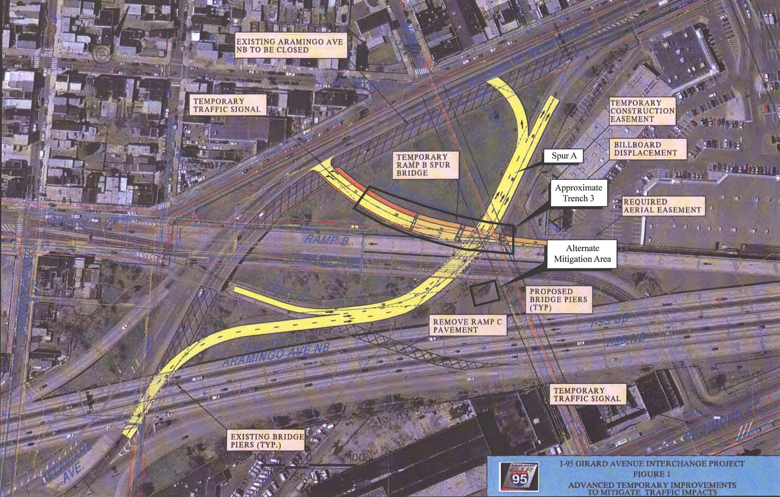
The earliest archaeological testing to be performed in the vicinity of the long-vanished Aramingo Canal was completed in September 2007, in advance of the construction of a temporary elevated traffic ramp within the larger Girard Avenue interchange of I-95 (designated Section GR0). Located to the south and southwest of the Aramingo Shopping Center, this ramp redirected vehicles exiting southbound I-95 at Girard Avenue onto Aramingo Avenue, and cut directly across the full width of the former channel, very close to where Norris Street once bridged over the canal (refer to Figure 1.2). Although historic maps and other documents informed members of the archaeological team that the canal had once passed through this place, no information at that time could shed any light on whether any part of the public highway had survived the sewer conversion process, the twentieth-century growth and development of the surrounding neighborhood, or the natural processes of decay. When researchers examined the original construction plans for I-95, anticipations were raised that at least some elements of the canal might be discovered through archaeological excavation (Figure 3.1). These technical drawings clearly indicated that, at least as of the mid-1960s, sections of the Aramingo Canal’s east and west timber walls still remained preserved below ground surface. The one gnawing question left unanswered by these plans, however, was how badly those walls might have been damaged during the construction of I-95.

Locations of Phase I/II Trenches 1, 2, and 3.
Initial Phase IB/II archaeological investigations within Section GR0 were limited to only those places along the Ramp B Spur alignment where significant ground disturbances were projected to occur. More specifically, testing was confined to the locations of one concrete abutment and two vertical support piers (Figure 3.2). Selection of these locations for subsurface exploration was based in part on historical documentation and partly on the results of earlier soil borings completed throughout this vicinity. Soil borings associated with both the abutment and Pier 1 produced possible evidence of intact historical ground surfaces beneath some 7–12 feet of unconsolidated fill material. Testing at Pier 2, on the other hand, was completed because it appeared to intersect portions of the western wall of the Aramingo Canal.
Testing was not performed at two other pier locations (designated Piers 3 and 4), situated to the east of Pier 2, because of a reassessment of archaeological potential and inherent technical difficulties. In terms of potential, Pier 3 was determined to fall squarely within the former prism of the Aramingo Canal, and was situated very near to the active Aramingo Sewer. As a result, this location was judged as being unlikely to produce significant information about the construction or operation of the canal, and very probably experienced substantial disturbance as a result of known sewer construction activities. Pier 4 was more promisingly situated nearer the east wall of the former canal, but was also located very close to an active fire hydrant and water main. Testing in these pier locations could have been completed, but not without involving significant disruption of the adjacent Aramingo Shopping Center parking lot, and with a less than mediocre chance of returning meaningful archaeological data. The Phase IB/II field methods are detailed in Appendix D.
Abutment and Pier 1 Testing Results
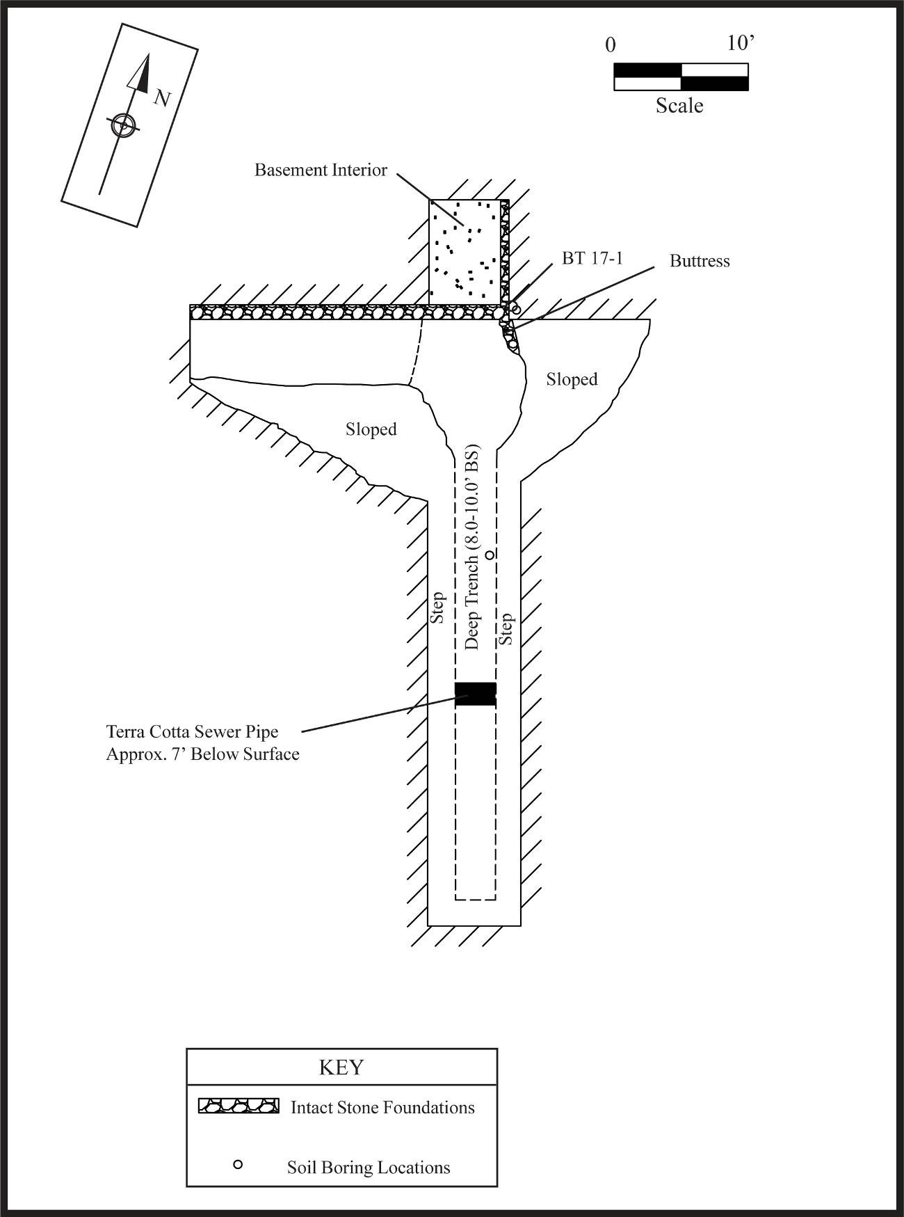
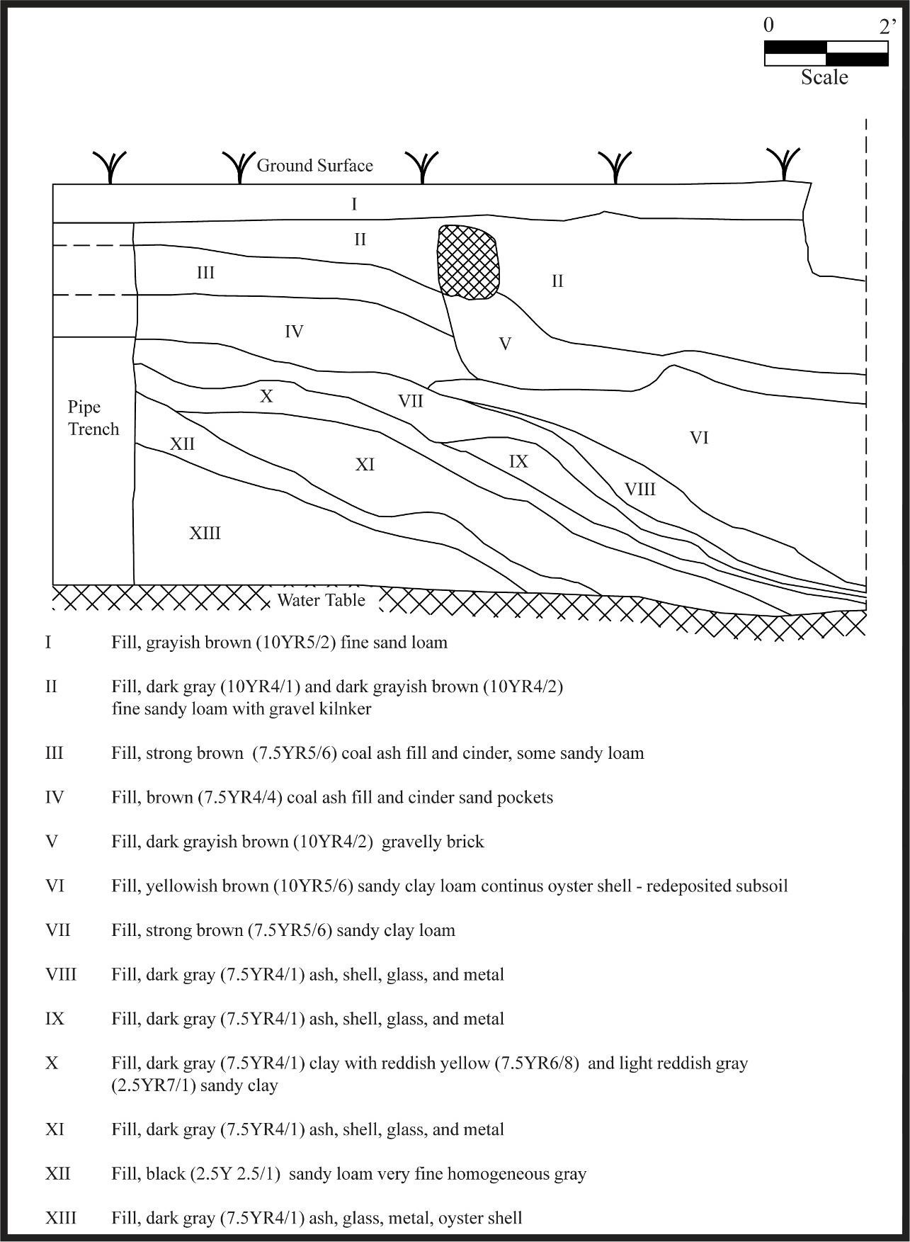
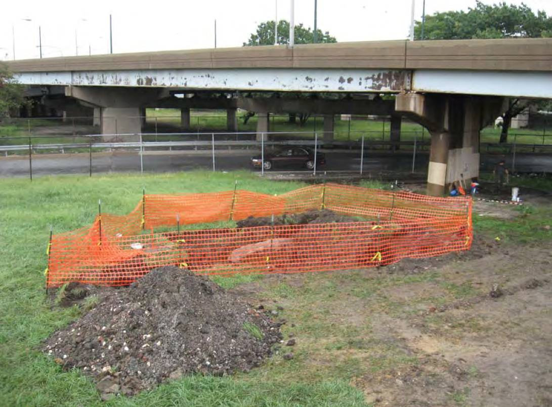
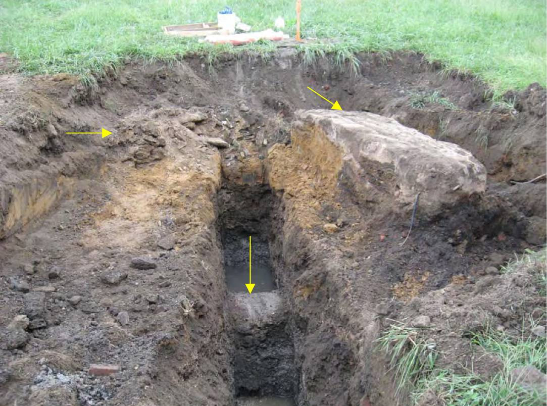
The western abutment and Pier 1 locations were situated, at the time of testing, within an open grassy field and fell within a section of the historic Girard (formerly Franklin) Avenue road alignment. Test trenches completed at these locations (designated Trenches 1 and 2, respectively) primarily encountered deep deposits of mixed historical fill, though in both instances preserved historic building foundations were also exposed at the extreme margins of the excavations (Figures 3.3, 3.4, 3.5, 3.6, 3.7, 3.8, 3.9, 3.10). Fill deposits extended to depths of at least 10 feet below ground surface and contained variable quantities of construction rubble, coal ash/cinders, and generally small to moderate amounts of nineteenth- and twentieth-century glass, ceramic, metal, and plastic artifacts. At approximately 8 feet below ground surface, groundwater was encountered that flooded the trenches. The combination of groundwater and constant slumping of the trench fill prevented the positive identification of intact soils or sediments in both locations.
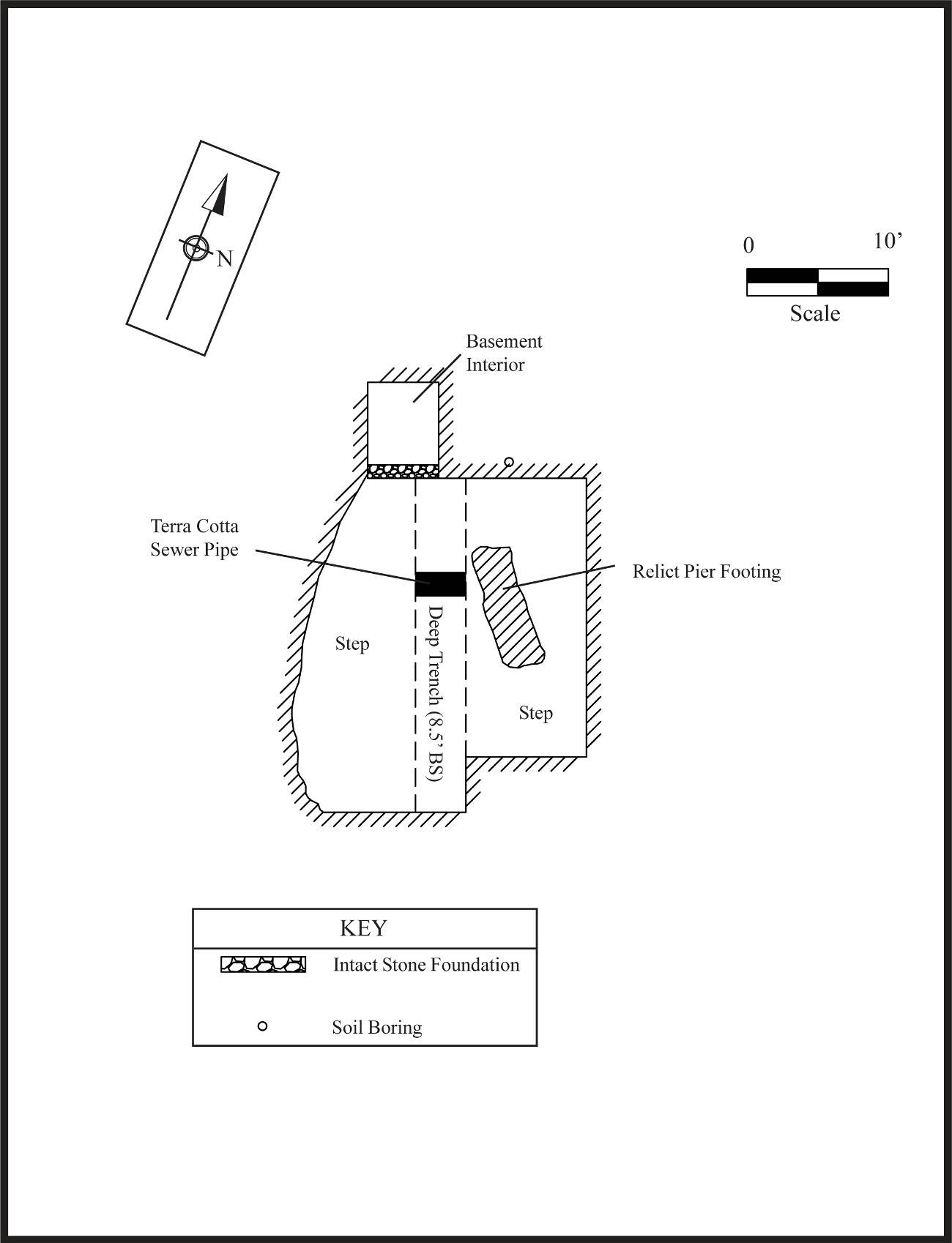
Both trenches also revealed evidence of more recent construction-related disturbance—a large, 2–3-foot-diameter terracotta sewer pipe (intact, but abandoned) was identified at or near the center of both test trenches. Trench 2 additionally exposed a single large concrete pier footing or truncated pier, located at nearly the exact spot where planned steel pilings were proposed for installation. The concrete footing measured approximately 2.5 x 9 feet in size, extended to an unknown depth below surface, and may have been structurally associated in some way with the former eastern extent of Girard Avenue.
At both test locations, historic stone building foundations were exposed at the northernmost limits of the excavations. These walls were well-preserved and first appeared between 1 and 2 feet below the current ground surface. Extensions of both test trenches determined that these walls represent the southern foundations of buildings that formerly lined the north side of Girard Avenue. Exposed remains also indicate that the interior spaces of both structures remain well-preserved just outside the points of impact for the planned temporary Ramp B Spur support piers; however, no evidence of intact artifact deposits was identified in association with these structures. Given that Ramp B Spur impacts to these buildings were thought to be relatively minor at worst, no further documentation was completed at the time. By the same token, these results did indicate that historic building remains and other archaeological deposits located to the north of the Ramp B Spur are extensive and well-preserved below the ground. Any future construction-related impacts to these portions of the GR0 project area/Girard Avenue interchange will require additional and more extensive archaeological documentation and evaluation.
Pier 2 Testing Results

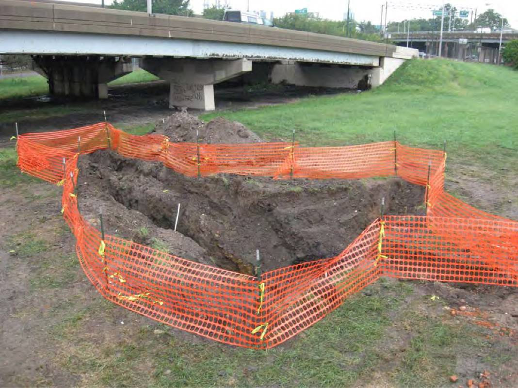
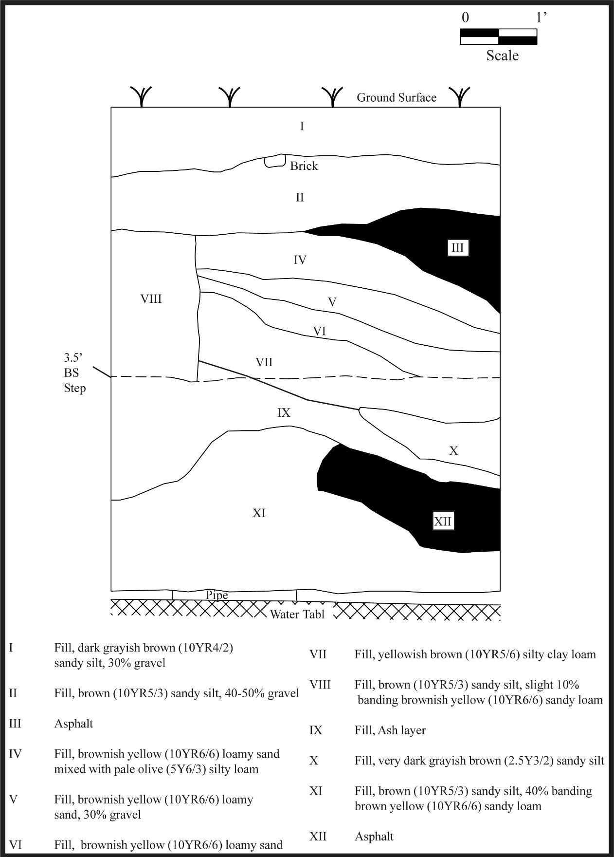
Trench 3 south profile.
Archaeological testing of Pier 2 began with the excavation of a single backhoe trench (Trench 3) that was gradually expanded to expose a series of canal-related features. Excavations at this location were performed in a very restricted space that was hemmed in by the existing Ramp A roadway to the south, the Aramingo Shopping Center parking lot to the west and north, and the elevated Ramp B roadway to the east. As with the first two trenches, excavations at Pier 2 encountered deep mixed fill deposits consisting of construction rubble (brickbats/concrete/stone rubble), multiple lenses of sandy soils, and a layer of asphalt fragments. These extended to depths of approximately 8 feet below ground surface before deposits of thick gleyed clay and sandy silt were exposed (Figure 3.11). Features exposed within the trench included a large stone bridge abutment associated with the former Norris Street bridge over the canal—a large, initially unidentified wooden construction that extended out perpendicularly into the former canal channel—and a remnant intact section of the canal’s timber west wall (Figures 3.12 and 3.13). Additional details of each of these structures are provided below.
Norris Street Bridge Abutment

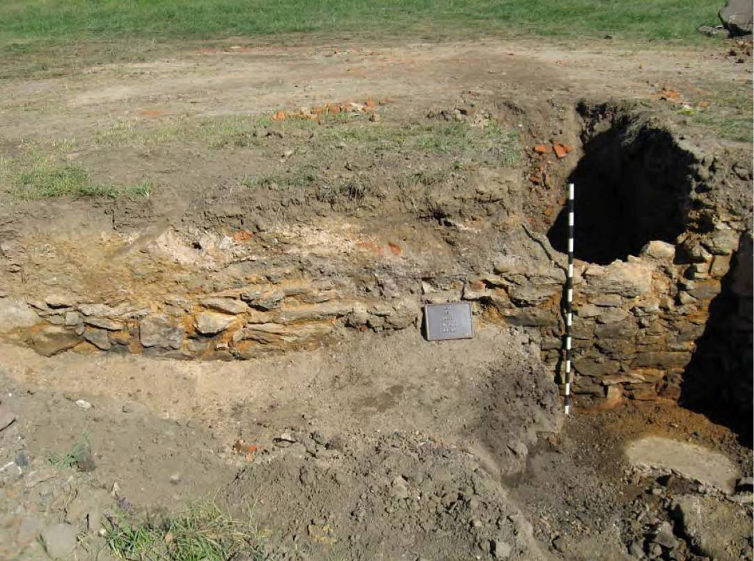
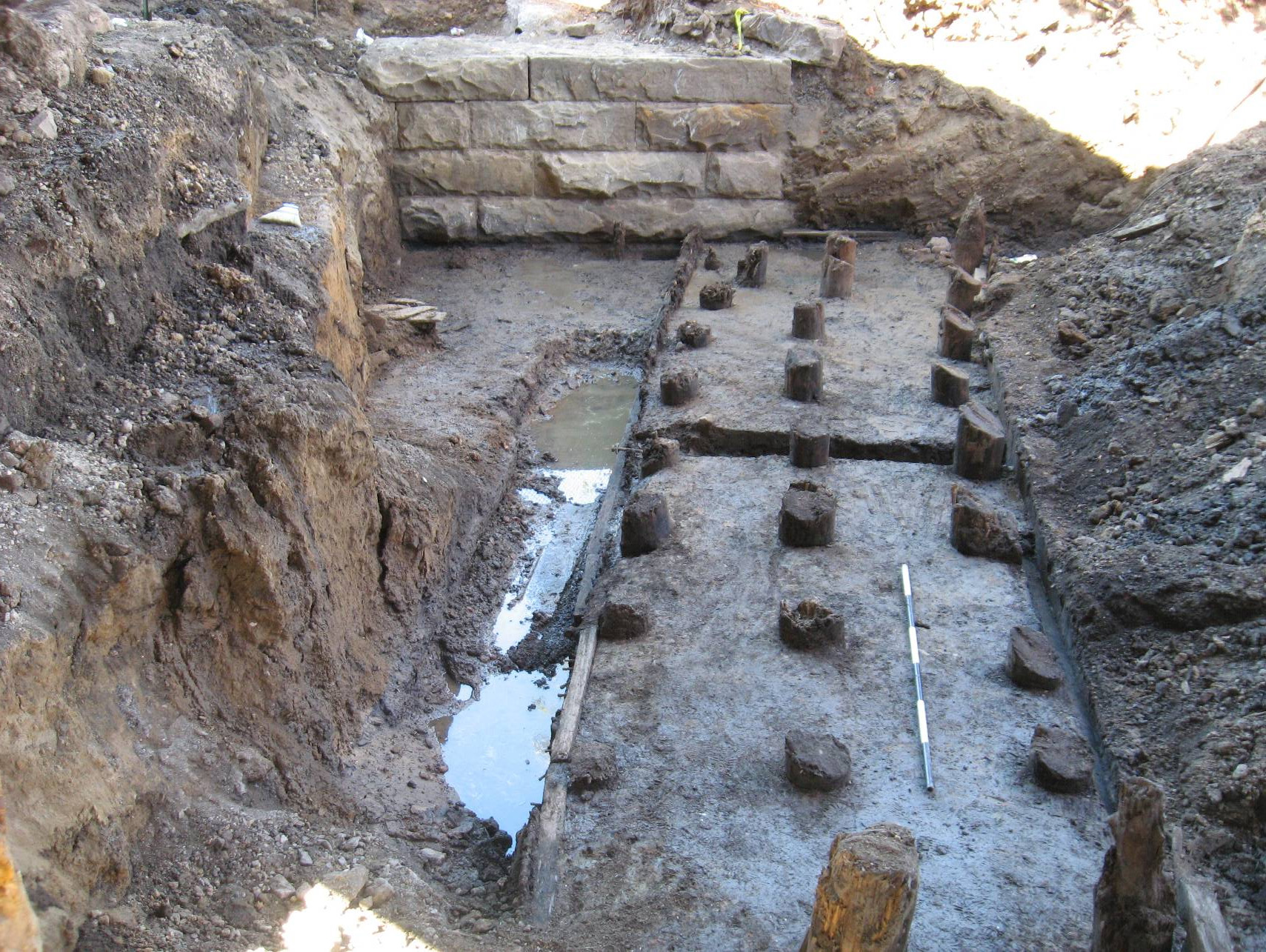
Detail of the stone abutment.
The Norris Street bridge abutment was first identified at a depth of some 2 feet below ground surface, and consisted of a series of mortared stone blocks with a rusticated exterior finish (Figure 3.14). In all, the exposed section of this feature measured approximately 12 feet long and 6 feet high. Individual blocks comprising it measured 2 feet thick, by 1.3 feet high, by up to 5 feet or more in overall length. Unfortunately, the full height of the abutment could not be determined, as the dense clay/silt fill at the bottom of the trench, along with excessive groundwater, prevented its full excavation. As indicated by a series of dislodged stones near the ground surface, the abutment also originally extended higher than documented, with the upper one or more courses of block having been disturbed at some point in the past.
.")
Photograph of the Norris Street bridge showing the stone abutment at left (Source: Philadelphia Water Department 1900-1902).
The few surviving photographs of the Aramingo Canal sometimes include images of other bridges in this vicinity, and those structures seem to have been built with similar stone abutments. Photographs of the Norris Street bridge over the canal clearly show the rusticated blocks used in the construction of this specific structure (Figure 3.15). In addition to the abutment, the northern extension of Trench 3 partially exposed a damaged—but otherwise apparently in situ—fluted iron column or support pier used to support the Norris Street bridge superstructure. Depictions of these columns also appear in surviving historic photographs of this bridge.
Post Structure

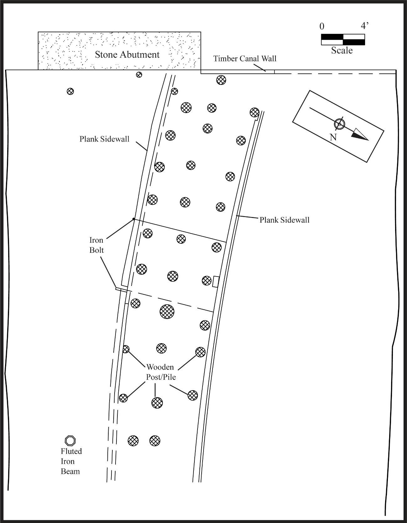
Detail of outer plank wall of bulkhead/coffer dam and vertical posts/piles.
This structure measured approximately 8.3 feet in width by at least 35 feet in length, and was constructed of three parallel rows of vertical wooden posts or piles, each approximately 0.8 to 1 foot in diameter, with associated wooden walls of heavy vertical planks attached to both the northern and southern sides of the posts (Figure 3.16). The outer walls were reinforced with iron tie rods that extended through the full width of the structure and were bolted at either end. The interior was filled with a thick gray clay or silt (Figure 3.17). The structure was not completely linear in construction, but rather curved or bowed outward very slightly in the downstream direction. Because of heavy groundwater infiltration, the full vertical extent of this structure could not be determined.

Detail of bulkhead/coffer dam with tie rod reinforcement.
Although the exact function of this post structure was unknown at the time of Phase IB/II fieldwork, subsequent research revealed it to be similar in general form to the description of coffer dams installed to facilitate draining of the canal and construction of the Aramingo Sewer just prior to and at the turn of the twentieth century.
The coffer dams… consisted essentially of two rows of heavy tongued and grooved sheet piling tied and braced and additionally supported by vertical and inclined piles, the space between the rows being filled with puddle and earth dumped in front and behind the sheathing… 1

Detail of cut posts in bulkhead/coffer dam.
As stated in Chapter 2, by 1895 the canal had been completely converted to a sewer and filled in north of the Girard Avenue/Norris Street intersection. Based on this information, the post structure identified in Trench 3 is believed to represent a remnant of the “bulkhead” or coffer dam that formed the northernmost extent of the Aramingo Canal channel as it existed during the final years of the nineteenth century. Many of the posts found in Trench 3 were cut off at approximately the same angle, suggesting that the structure was later removed, possibly when the last southern sections of the sewer were built, beginning in 1900 (Figure 3.18).
Canal Wall

View of remnant timber lining of the west canal wall.
Explorations along the base of the bridge abutment eventually exposed a series of truncated wooden members of the western timber wall of the Aramingo Canal itself. These elements only appeared at the very bottom of the trench excavation, at about 8 feet below ground surface, and consisted of a series of vertical posts aligned along the face of the abutment, as well as associated horizontal logs or beams extending northwest beyond the limits of the abutment and Trench 3 (Figure 3.19; see also Figure 3.12). Unfortunately, these elements of the canal wall were exposed at the depth where groundwater entered the excavation, and so were largely identified in a submerged state. Persistent groundwater infiltration into the excavation prevented any detailed documentation of the exposed canal wall.

Alternate mitigation area southeast of Trench 3.
Given the apparent archaeological significance of the Aramingo Canal, and the limited space available within the study area, URS archaeologists requested—and received—permission to conduct additional testing outside of the Pier 2 location in order to identify other equally well-preserved sections of the canal (see Fig. 1.2). These supplementary tests were completed in an open area situated between the Girard Avenue and southbound I-95 elevated roadways, approximately 100 feet southeast of Trench 3 (Figure 3.20), and sought to find an alternative area where more intensive investigations of the canal might be undertaken. A single test trench excavated in this area exposed a portion of the eastern canal timber wall at a depth of 8 feet below ground surface (Figure 3.21), and confirmed that this area would be an appropriate place for conducting more intensive data-recovery investigations.

Detail of canal wall timber and iron spike found in the alternate mitigation area test trench.
Initial Phase IB/II investigations at the Pier 2 location ultimately were able to demonstrate that construction of the planned Ramp B Spur would result in impacts to well-preserved sections of the Aramingo Canal. The canal was considered to represent a significant historic resource and Phase III archaeological investigations were recommended in order to more thoroughly document the construction of the canal prism and any associated artifact deposits and/or features. On September 17, 2008, a field meeting to review findings was held within the GR0 project area and attended by representatives from URS, PennDOT District 6-0, and the PHMC. Based on discussions during that meeting, PennDOT and PHMC representatives concurred with recommendations regarding the need for further investigations, and also verbally approved URS plans for an alternative mitigation strategy for the Aramingo Canal. In accordance with that strategy, URS submitted a formal data-recovery plan (Appendix B), and PHMC concurrence was documented in a letter dated March 6, 2008 (Appendix C).
References
- City of Philadelphia (1902). Third Annual Message of Samuel H. Ashbridge, Mayor of the City of Philadelphia, with Annual Reports by William C. Haddock, Director of the Department of Public Works, and of the Bureau of Surveys, Year Ending December 31, 1901 ↩